Queen’s VEX U Robotics

2023/24 Engineering Notebook - Over Under
“One person can build a hut, but thousands together can build a skyscraper!”
Queen’s University, Kingston, Ontario, Canada
With special thanks to:
![]()

“One person can build a hut, but thousands together can build a skyscraper!”
Queen’s University, Kingston, Ontario, Canada
With special thanks to:
![]()

|

|

|
|

|
|
Welcome to QVEX! I am excited to present the results of our passionate and talented team, and hope you will enjoy reading about our progress thus far!
My name is Theo Lemay, and I am the 2023-24 President of the Queen’s VEX U Robotics Team, otherwise known at Queen’s as QVEX. I’m in 3rd-year Mathematics and Engineering at Queen’s, with a specialization in Systems and Robotics. This year, I’m leading our team of over 80 members to excel in competition, engineering design, and education.
I’ve been doing VEX Robotics for over 6 years, and it has transformed my life and opened up so many opportunities. By taking on the role of President at QVEX, I hope to give back by sparking the same passion in others, and I believe design teams are one of the best ways to do so!
Founded in 2019, QVEX is an award-winning competitive robotics team under the Engineering Society and Alma Mater Society. With over 80 interdisciplinary members from engineering, commerce, and science, QVEX consists of 4 Vice-Presidents, 5 Senior Technical Leads, 20 Technical Leads, and over 50 general design members.
Last year, the team achieved some huge milestones, placing 1st in Canada and reaching quarterfinals at Worlds after starting the season from scratch. This year, QVEX is focused on four key goals, consisting of Competition, Education, Outreach, and Long-Term Governance. While the team has dreams of excelling on the world stage, providing real-world engineering experience and teaching professional design practice is foremost in the team’s mission. For this reason, significant effort is placed to promote awareness of robotics and engineering. Finally, developing a solid foundation and framework for the team is crucial for its long-term success.
The following notebook contains all relevant information about QVEX. I am beyond excited to see the education and innovation we achieve throughout this year’s competitions. On behalf of QVEX, thank you for reviewing our notebook.
Sincerely,
Theo Lemay, QVEX President 2022-2023

The Queens VEX U Robotics Team (QVEX) is an award-winning competitive robotics team under the Engineering Society and Alma Mater Society. With over 80 inter-disciplinary members from engineering, commerce, and science, QVEX consists of 4 Vice-Presidents, 5 Senior Technical Leads, 20 Technical Leads, and over 50 general design members. The team was founded in 2019 to revolutionize engagement in robotics at Queen’s, while also developing a globally recognized competitive program.
In the 2022-23 season, QVEX experienced incredible growth, starting with three core members, growing to over 40 members throughout the season, and finishing with a core of 20 dedicated members who are now all part of the executive team. In one short year, QVEX finished as a quarterfinalist in its first-ever VEX U World Championship, ranked as the best university team in Canada, and won the Excellence Award at Nationals. The amount of passion and talent on the team is enormous, and the team is poised for another year of growth.
In the 2023-24 season, QVEX is focused on four key goals, consisting of Competition, Education, Outreach, and Long-Term Governance. While the team has dreams of excelling on the world stage, providing real-world engineering experience and teaching professional design practice is foremost in the team’s mission. For this reason, significant effort is placed to promote awareness of robotics and engineering. However, QVEX is on track for an extremely competitive year and is estimated to be top 10 in the World, and top in Canada. With the addition of 60 new members and the core of 20 experienced members, QVEX extends a warm welcome to all students, embracing a wide array of skills and experiences.
We pride ourselves on our diversity and the unique skills our members bring to the table, from various ages, races, and genders. We strive to emulate an engineering firm and maintain a family-like environment while providing opportunities for interpersonal development and skills outside of engineering. Aside from technical teams, our team includes members handling finance and logistics, outreach, and sponsorships, from various faculties such as computer science, engineering, and film.
QVEX strives to create well-rounded engineers, capable of working well in both a team environment and as an individual, who will be able to apply new skills to real-world engineering projects. This is done by giving students equal opportunity to contribute and learn, regardless of previous experience and knowledge. We seek to create a passionate environment where all members can give input, develop soft and technical skills, and feel comfortable in an inclusive community.
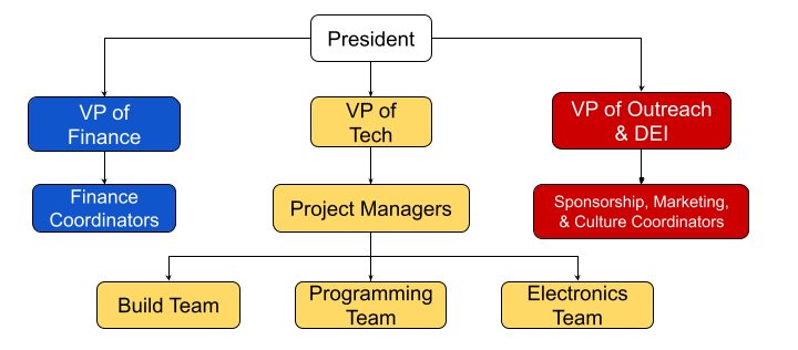
The president is hired on a yearly basis, and is responsible for selecting the Vice-Presidents (VP), and project managers (PM). In addition to this, the president is the main connection to the faculty and engineering society, runs general meetings, aids in robot design and construction, and assists VPs and PMs with tasks such as connecting with a sponsor or taking on additional work from a member too busy to complete their project.
Below the president fall the VPs, who are responsible for selecting and managing the PMs. Similar to the president, VPs must apply for a job posting and go through an interview process in order to secure the position.
Project managers are the day-to-day managers of the team. They are chosen based on an application process and facilitate the production of the robots. PMs break down the project into tasks, supply tasks to their members, and maintain the project timeline.
A visualization of this structure is shown below.
Team communication is spearheaded on Discord, an online social platform allowing the team to communicate via voice, text, and video, along with supplying the organizational capabilities to properly break down the team structure and the various projects the team tackles. Team members are expected to check the server at least once a day, to stay up to date with the team’s progress, and any important news regarding the team.
If something arises that the team president deems highly important, an update will be sent via email in addition to signalling the team on Discord. When signing up for the team, members provide their student email, which is then put on a mailing list, for important updates.
Communication does not solely lie within the team, it expands to teams across the globe. This is done through social media, such as YouTube, and Instagram. For example, QVEX continues to release tutorials and documents to aid other teams in the creation and improvement of their robot, alongside other teams to help us improve our own.
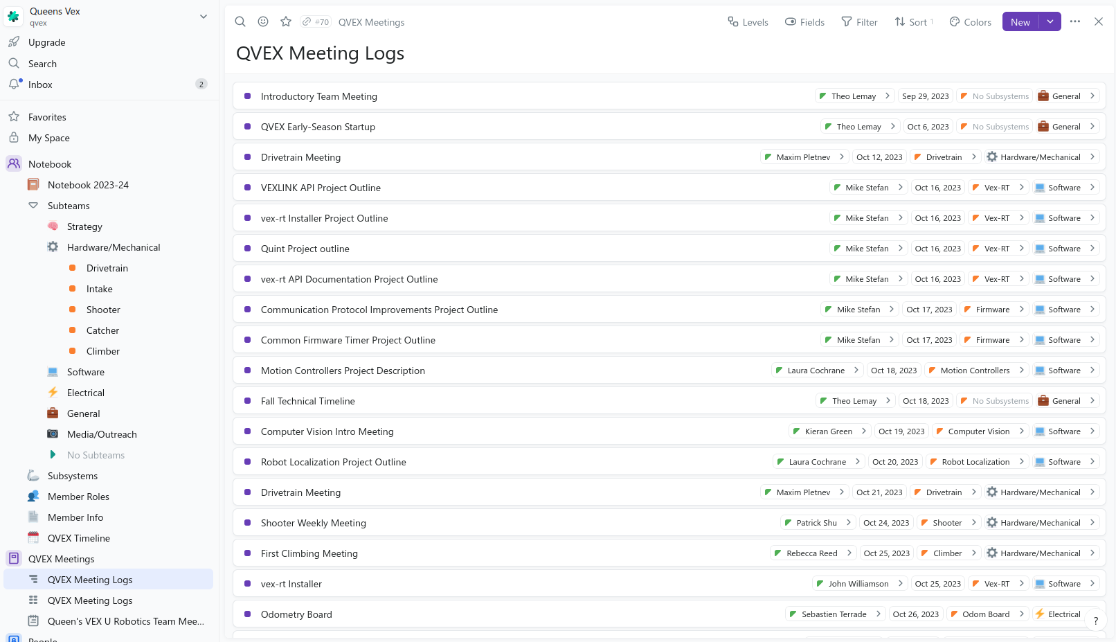
To manage the design process of such a large team, a novel notebooking approach was developed. It consists of four parts:
An interactive view of the database is available at: https://queens-vex.fibery.io/@public/Notebook/.
A screenshot of the database is shown below:
When subteams have a meeting, they fill out the meeting log form at http://log.qvex.ca/, also shown below.
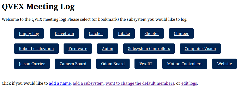
The subteam can then describe what happened during the meeting. This meeting log gets added to the database, and is also summarized by AI and sent to a channel in the discord server.
Finally, a script is triggered which runs a cloud worker that compiles the document together and produces a rendered PDF.
 Theo Lemay President 3rd-year Applied
Mathematics & Engineering
Theo Lemay President 3rd-year Applied
Mathematics & Engineering Koen Dyck VP Finance 3rd-year Applied
Mathematics & Engineering
Koen Dyck VP Finance 3rd-year Applied
Mathematics & Engineering Taylor Hambleton VP Communications &
EDII/AS 3rd-year Applied Mathematics & Engineering
Taylor Hambleton VP Communications &
EDII/AS 3rd-year Applied Mathematics & Engineering |
 Michael Cassidy VP Tech 2nd-year
Computing
Michael Cassidy VP Tech 2nd-year
Computing Cassandra Koitsopoulous VP Outreach 3rd-year
Engineering Chemistry
Cassandra Koitsopoulous VP Outreach 3rd-year
Engineering Chemistry |
VEX Over Under puts two teams, each with two robots, on a 12’x12’ field, competing to score the most points. The field includes 60 triballs–4 as preloads, 44 as match loads, split between the teams, and 12 beginning on the field. It also contains two elevation bars, four matchload goals, and two goals, all split between the teams. The game is divided into the “Autonomous Period” and the “Driver Controlled Period”. Points scored during the autonomous period carry over to the driver control period.
During the autonomous period, which lasts 45 seconds, points are awarded at round completion if specific requirements are met. A point is awarded if a team scores an alliance triball and contacts the elevation bar. A bonus of 8 points is awarded to the team that scored the most at the end of the period.
The driver-controlled period, lasting 75 seconds, has the team trying to outscore their opponent in multiple ways. Five points are awarded for each triball scored in a goal, and two points are awarded for each triball in the opponent’s zone. Finally, points (up to 20) are awarded for each of the four tiers of elevation.
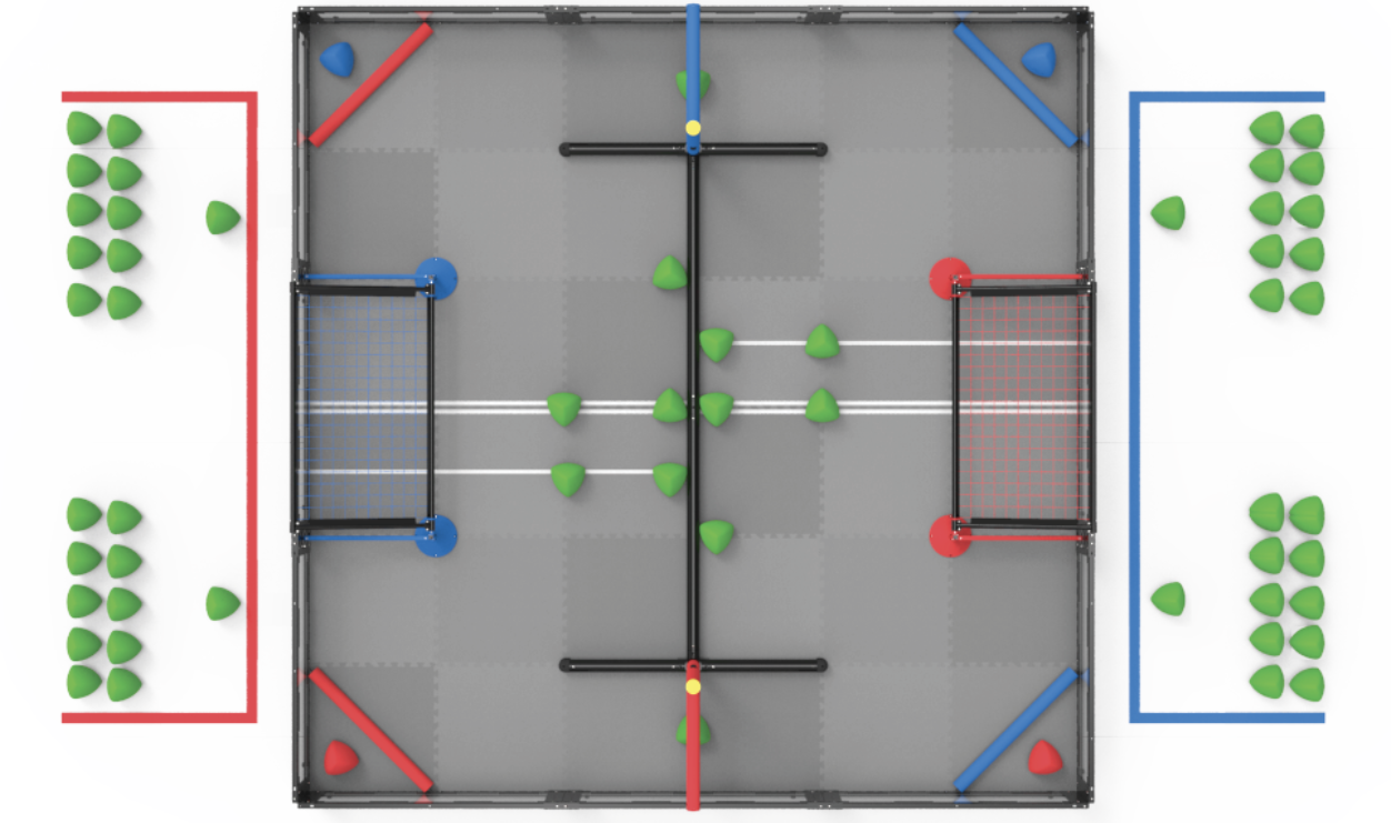
The field features two opposing scoring zones separated by a roughly 3” tall bar, each with two zones for teams to match load.
The match loading zones are separated from the field by a 30” long 2.5” diameter bar, from which bots cannot cross but can intake triballs.
Scoring zones are connected by two gaps under the elevation bars, which are 11.63” tall. To access both sides of the field, a robot must be under this height or capable of driving over the 3” bar.
White tape separates the left and right sides of the field and marks the area that robots can access during the autonomous period.
Triballs can be pushed under the roughly 5.78” tall goal post, which counts as 5 points. Other triballs in the offensive zone count as 2 points, and alliance triballs count as 5 points to the team of their colour, regardless of which net they’re scored on.
The two posts fixed to the field can slide up, meaning some force is required to score a triball.
Triballs can only be removed if both robots of the scoring team are in the defensive zone. One of these robots contacting the middle bar counts as having it in the offensive zone, meaning the team can no longer un-score triballs.
Towards the end of the driver period, robots can climb their elevation poles, and the score given is based on the robot’s lowest point at the end of the match.
Points given are compared with the highest climb being awarded 20 points, the second highest getting 15 and so on, down to 5 for the lowest.
Two robots at the same climb height are awarded equal points, with the next highest climb being awarded one tier lower.
Robots that do not climb are not considered while scoring the climb.
Robots cannot contact robots touching the ground or the golden bar cap on the vertical elevation bar.
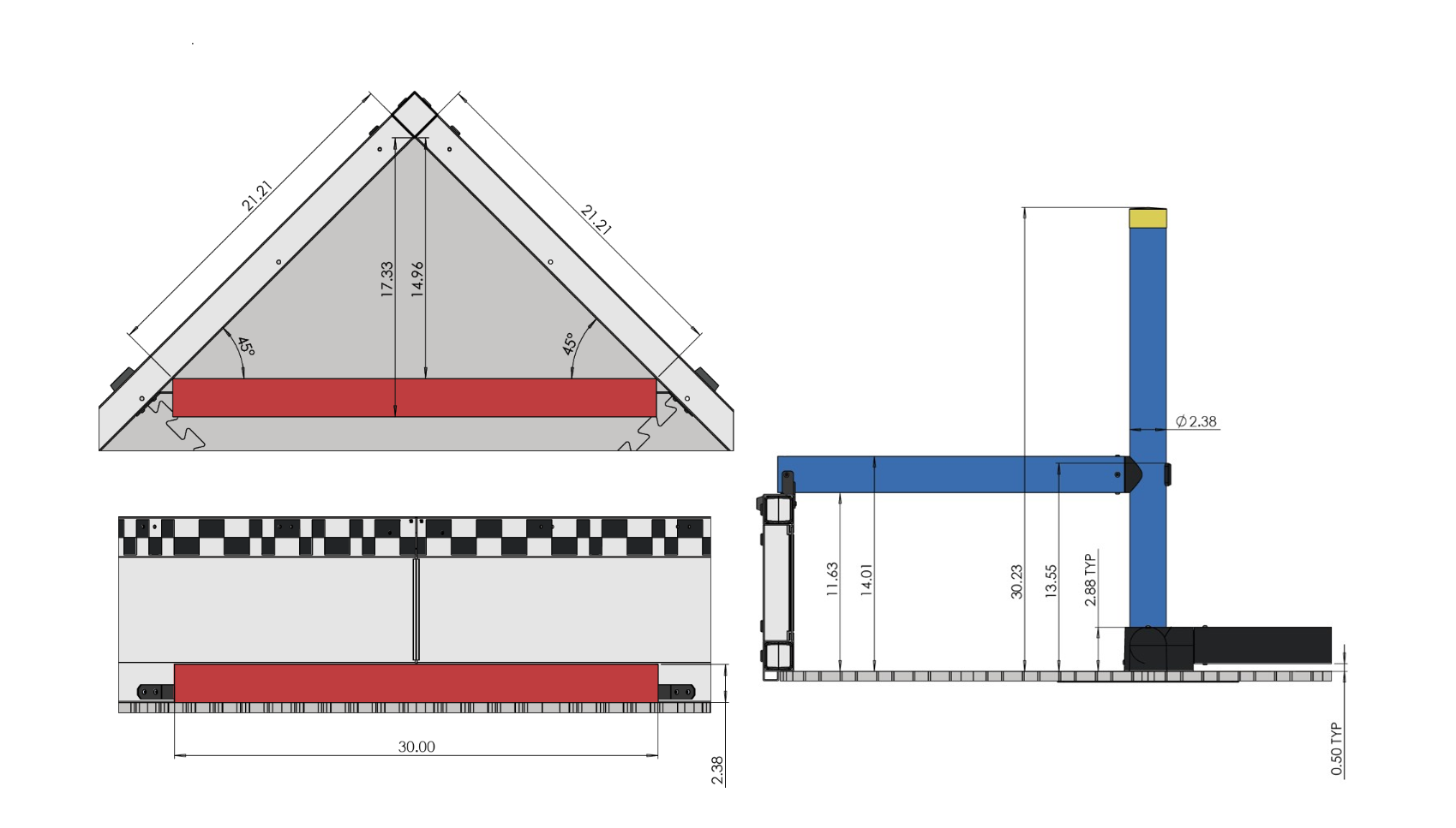
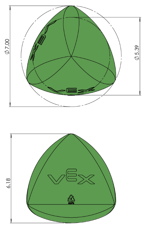
Triballs are a constant-diameter pyramid-like shape with rounded sides and a rigid plastic exterior that weighs approximately 110 grams.
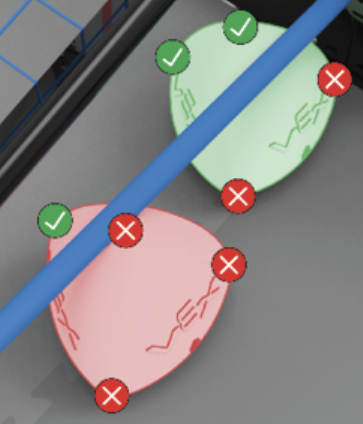
Triballs are scored when two of the four corners are under the outermost part of the net, as shown to the right.
During skills, the team’s alliance balls can be placed at any point on the field if unscored.
Once we completed the initial analysis of the game’s field elements and got a feel for how to get practical scoring underway, the team had some meetings to discuss potential strategies. The main factors affecting said strategies were the game’s autonomous phase and the triballs’ movement.
Early on in the season, it was desired to get an excellent autonomous strategy to get ahead of opponents once driver control started. Since this year’s game’s scoring elements mostly have to be introduced into the game as individual match loads, it was determined that a large portion of those triballs should be introduced during the autonomous phase of the game so that the bots can focus on other objectives during driver control. There are 22 triballs for each team as match loads, so ideally, above half of that will be depleted and scored during the autonomous phase.
Another deciding factor for our bots was how moving triballs would be done. From what the field looks like, the two viable options are through the air over the middle PVC barrier and pushing it through the outside beside the elevation bars. So the team initially went with a puncher shooting design to shoot the triballs from one zone to another, effectively going over the middle barrier. This will be complemented with one of the bots having a catcher mechanism, ideally catching every triball in the offensive zone shot from the shooter bot and out-taking the triball in the net to score top points. On top of that, our robots will have some side wings that act as a plow to push triballs on the outside towards the goal. This is to give variability to our strategy in case one method becomes more favourable. Other teams have proven these strategies viable with their mechanisms, but the team hopes to do so better.
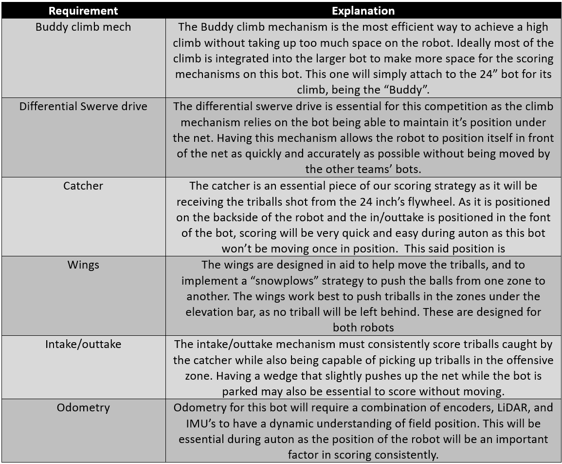
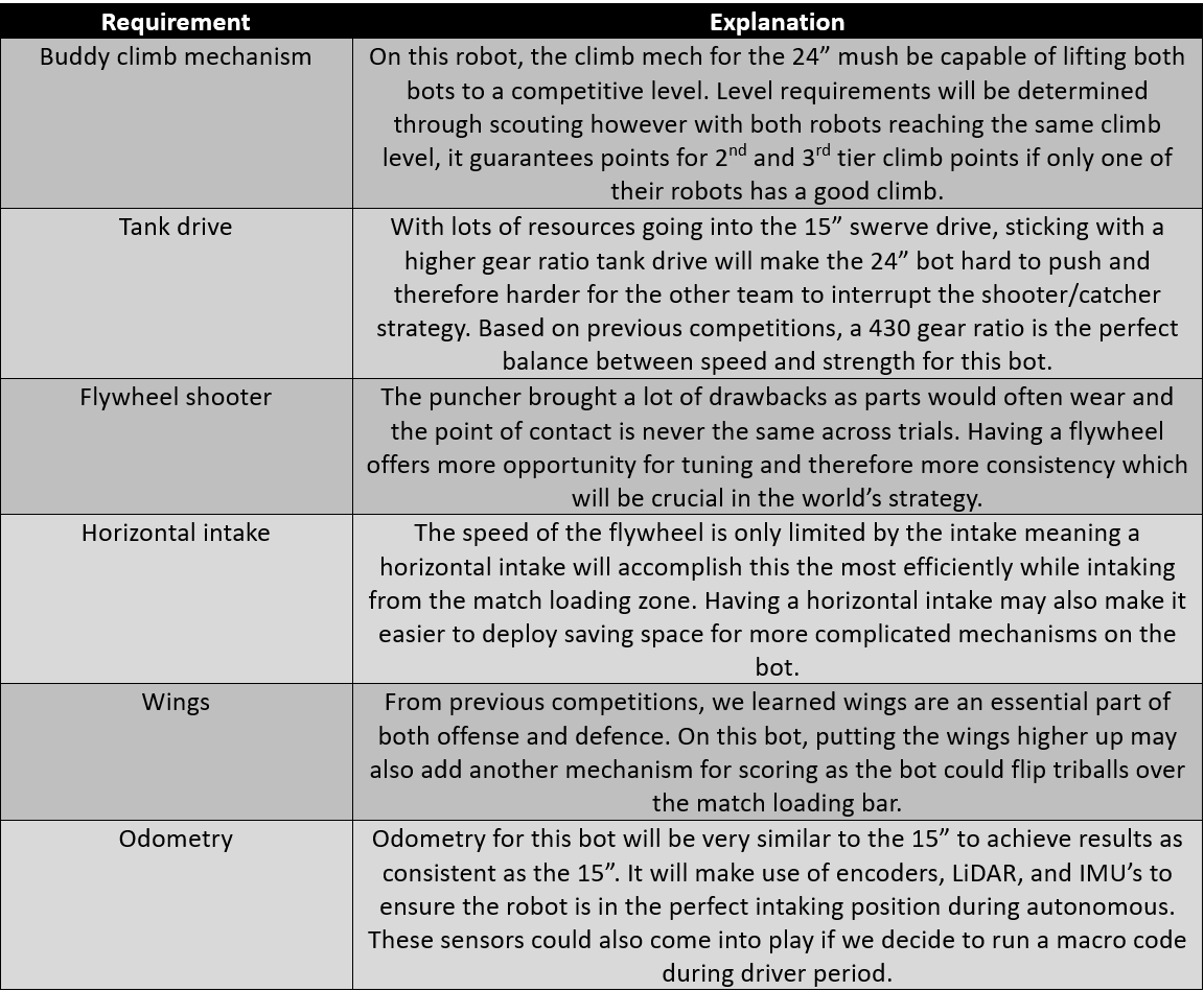
Two tables were made based on our experiences at competition with how our robots performed and strategies that we have seen other teams implement. The tables outline required features for world bots based on designs we plan on implementing and possible changes that need to be made. Some decisions can be seen in other subteam sections with weighted evaluation matrices to match.
Going into this season, our goal was to expose a new set of creative members to all aspects of VEX, and part of this meant starting with a relatively simple design. Hosting QRC and having the team structured with many smaller sub-teams significantly helped with member engagement. It also significantly helped with the progress of the robots, allowing for more iteration and, therefore, more consistent designs. The lack of experience with VEX proved to be a benefit as the designs for the world’s bots are very original and take advantage of mechanisms and coding that rarely see use.
Discuss our world goals (ambitious) vs competition goals (ease of implementation) with a decision matrix.
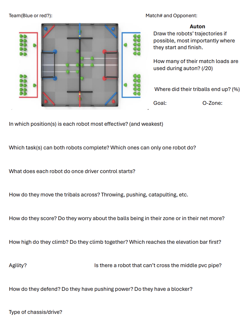
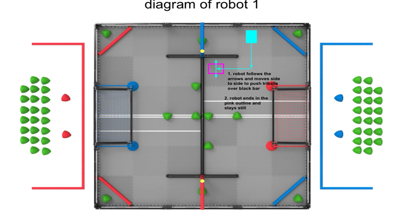
The scouting side of strategy is critical to the team’s success, as it gives our drive team a lot of knowledge of their opponents before our matches. As they get played, scouts will use the scouting sheet as an aide-mémoire to build strategies against their corresponding team and provide strategy leads/drive team members a visual representation of robot routes/functions, providing a deeper explanation of the opponent’s behaviour. The scouting sheet was made with a vision of including most of the questions the drive team would have regarding strategy for scouts to think about while watching matches. For example, the figures below show the scouting sheet, followed by two examples of how one of our scouts drew out an opponent team’s autonomous routes for both of their robots.
QRC Analysis & Goals
For many reasons, the Queen’s Robotics Cup challenged the strategy aspect of the team’s functionality. The scouting sheets were made, but as the cup was hosted at our university, many team members attended, and since many of them wanted to be more involved with the team, they were scouts. It was to the point that there were twenty scouts for only five teams at the competition, and it was too much to process in such a short time. Multiple other factors include there wasn’t any primary constructive system in place for scouting to be communicated to the drive team, and given it was a small tournament, there wasn’t much time between matches, so the drive team prioritized the robot’s maintenance with our pit crew. Another thing to consider is that the early stage of the season meant our robots were far from perfect, and they faced many challenges during matches, like the intakes not working, some pneumatic functions failing, our autonomous strategy having some malfunctions, etc. It made it hard to visualize a concrete strategy without our robots giving us a taste of our capabilities.
To this point in this year’s game, there were few defined strategies to watch out for early in the season, meaning we didn’t have a good idea of what our strategy had to accomplish. Paired with the technical malfunctions, our biggest priority at QRC became learning how teams would play and what we could do for future competitions.
Have a bot under 11” to transfer triballs under the elevation bar and stop other teams from doing the same.
Playing defensively makes scoring exponentially harder for other teams and gives your team more opportunities. It can be accomplished with more robust drivetrains and bigger wings.
Clearing your zone of triballs quickly allows your defensive bot to match load and put more pressure on their team’s defence.
There was no need to commit more resources to the climb; having an A climb would keep us competitive.
The most significant oversight was how teams would use the gap under the elevation bar to funnel match loads into the scoring zone consistently. A bot under 11” tall allows for a much more consistent method of transferring match loads, particularly in earlier competitions with less advanced robots. Knowing when to match load and being able to play consistent defence was also crucial to success in this competition. We learned that most strategies to this point revolved around having a bot that could score match loads in the offensive zone.
Compared to QRC, the West Virginia competition went a lot better in every aspect. There were lots of conversations about what to improve in terms of strategy and scouting for this competition, including a new member of the drive team working with the strategy lead to get a constructive and clear plan for the drive team’s comprehension. Thankfully, there were also longer times between matches compared to QRC, so the drive team had some time before every one of our matches to have a little huddle to make a strategy. With only seven scouts this time, communication wasn’t cluttered or interrupted. Everyone knew who to talk to and, most importantly, when. The fact that we had much-improved robots got us 2nd in the competition/skills and a ticket to the world. For this competition, once the match schedule came out, we mapped out times to meet with the drive team to make some strategy and let the drive team know how the other robots were functioning and their movements.
Learning from QRC, we understood better the importance of having a very defensive bot, which meant lower-scoring games but many more wins. Refining the intake and puncher mechanism helped us have an edge coming out of autonomous, meaning we could more efficiently transition into clearing our zone and pressuring theirs. These improvements resulted in a second-place finish, world qualification, and a more impressive skills score.
Having identical bots necessitated developing a more efficient method to cycle between match loading and scoring. We did a great job at defence, which didn’t leave much for the offensive bot to do once the scoring zone was clear.
Improving our autonomous period would mean scoring more triballs rather than leaving the offensive zone to be cleared by their defensive bot.
Match loading can also be done as the opposite team is going for their climb, which can be capitalized on if they have a slow climb.
After our successful competition in West Virginia, there was a meeting to talk about how things went at the competition, and overall, the team was happy. However, there is still room for improvement on the strategy side. The drive team found that the strategies provided were not as intentional as expected and more observation-based, meaning we need to be more precise with methods for our robots to win even more. For example, when one of the robots was defending, the other robot had nothing to do except for an uncontested match load zone. Our offensive robot had nothing to do once all the balls were gone, losing the precious momentum built up to that point. With that being said, the strategy will be a lot more precise at worlds, giving each robot specific tasks to counter the opponent’s robots throughout the match.
During the 2023-24 Over Under season, the mechanical team is roughly split up into 5 sub teams, including:
Each sub team is responsible for the end-to-end design and manufacturing of their subsystem. This section introduces each subsystem, its goals, its design process, and its timeline.
|
|
|
|
|
|
Requirements: the drivetrain subteam is dedicated to creating a mechanism that can:
Drive over the center bar.
Fit within the volume specified (15” × 15” and 24” × 24”)
Use a maximum of eight VEX motors
Maneuver quickly and be agile in a game setting
Push opponents around and be strong enough to prevent being pushed
Allow space and connection points for the other subsystems (catcher, shooter, etc.)
Pontoons: With the initial decision of a tank drive, including pontoons as part of the frame seemed feasible for both the strength and rigidity of the drivetrain. These pontoons house the wheels as well as the gears connected to the motors to provide shielding from any bots or other obstacles. They consist of four identical trapezoidal aluminum plates, which are connected in parallel in pairs, each making up one pontoon (two for each side of the bot). They have all the necessary holes to connect the driving axles and the gear axles to drive the bots. Still, they also hold some of the essential connection points of the drivetrain to hold it together and to attach other elements of the robot. To hold the pairs of plates together, thick and rigid metal blocks are situated between the plates at the front and back.
Motor Mounts: On the inside face of each pontoon are two sets of motor mounts. These motor mounts hold two motors together and must match the motor + casings’ profile. To do this, measurements from the motors and casings with all necessary dimensions were taken so the mounts could fit within the motor profile with minimal room for the motor to move around. The design also made sure that there were the necessary holes such that the motors could be directly attached to the mounts and the mounts could be attached to the pontoons, both with screws.
Geartrain: A geartrain, or more technically, a transmission, couples motors together and outputs torque to every wheel on the pontoon.
Cross Braces: Cross braces were used to connect the pontoons and hold the various added subsystems on top and behind the drivetrain. Because they were the anchor to almost the whole robot, they were designed to be strong and allow for other subsystems to be attached.
Design Process: The initial design considered discussing and weighing the different drivetrain types regarding maneuverability, speed and other factors (see WEM below). It was decided that the tank drive was best for the first half of the year as it was relatively simple but powerful, allowing us to push other bots around. Many iterations were done throughout the design and CAD process, changing up some of the parts above. Once the CAD and manufacturing were done, we tested alongside some software teams to test our drivetrain and their code simultaneously. We used the QRC competition as an opportunity to test and understand the flaws of the design. Using the main issues we spotted during this competition and in preparation for Worlds, the drivetrain team split up to work on the 24” tank drive and the 15” drivetrain. Using what we learned, many iterations were done to allow our robots to be more agile and able to cross the center bar.
All standard drivetrain styles were considered for the robots. These basic designs have been vastly explored in previous competitions. The possible designs are as follows.
Tank Drive: This design involves a forward-facing omni wheel in each corner and a traction wheel in the middle. Eight motors, four per side, would drive the wheels. The design generates a lot of torque but cannot strafe (move sideways). However, the design’s basis makes it difficult for opposing bots to push it from the side.

X Drive: An X drive has four omni wheels, all at 45-degree angles, resulting in high maneuverability and speed. This design would make a highly nimble robot that can quickly get anywhere on the playing field. However, it may not drive straight when there is an imbalance of weight.

H Drive: H drives incorporate five omni wheels, one forward-facing in each corner and one across the center. The center wheel allows the robot to strafe but also allows an opposing robot to push it from the side. The design is still fast, but the wheel in the center can be challenging to access, presenting some maintenance problems during competitions. This also results in at least one extra motor to drive the center wheel.

Square Drive: A square drive has four forward-facing omni wheels, one in each corner. This is the most basic drivetrain, but it is easy to push and generates an average amount of torque.

Swerve Drive: This design uses two motors to rotate and turn an omni wheel on each of the four corners. It has the benefits of a square drive and an x drive as it can change the orientation of each wheel when necessary to vary speed and torque. While pushing is easier than a tank drive, it can turn its wheels to make pushing harder than a square drive.

The generated concepts were then evaluated using a weighted evaluation matrix, which can be found below. The following criteria were weighted based on their criticality to the design’s functionality.
Speed: This criterion looks at the speed that the drivetrain can produce. This category is important because it will dictate how quickly the drivers can react to the other team during the match. A quick reaction to the other team will optimize the robot’s ability to score and defend, which is why it receives a weight of 4.
Power: Power is the evaluation of the drivetrain’s ability to push other robots. This can be estimated through the torque generated by the wheels. This had the highest weight as it was determined that it was very important that our robot would be able to overpower other robots and also make it over the center bar.
Strafe: Strafing is the drivetrain’s ability to strafe back and forth. It is low-weight because it is less important than maneuverability. Since it is not as crucial as maneuverability, it receives a weight of 2. If a drivetrain can not strafe, it gets a score of 1.
Maneuverability: The ease with which the robot can turn. This category has a moderate weight as the robot needs to be able to maneuver precisely during matches. It also allows the drivers to react quickly to the other team; thus, it receives a weight of 3.
Maintenance: This criterion evaluates the ease of maintenance on the drivetrain, including frequency and accessibility. This is an important category as there are many mechanisms and little time between matches, so the pit crew must be able to perform drivetrain maintenance quickly with few complications.
Innovation: As part of our overall goal, an innovation factor was incorporated into the selection process. It evaluates the difficulty of the design and how its incorporation will set our robot apart from other teams. It is not weighed heavily because functionality is still the most critical aspect of the design.
Below is the completed evaluation matrix indicating each criterion’s scores for each design.
Criteria |
Weight |
Tank Drive |
X Drive |
H Drive |
Square |
Swerve |
Speed |
4 |
4 |
5 |
4 |
4 |
5 |
Power |
5 |
5 |
1 |
4 |
4 |
4 |
Strafing |
2 |
1 |
4 |
3 |
1 |
5 |
Maneuverability |
3 |
3 |
5 |
3 |
3 |
4 |
Maintenance |
3 |
4 |
2 |
2 |
5 |
1 |
Innovation |
1 |
2 |
4 |
3 |
1 |
5 |
Total |
|
66 |
58 |
60 |
63 |
70 |
The tank drive was initially selected due to its high scores in power and speed. It allows our bots to push others around while being relatively maneuverable. With an easy manufacturing process and lower maintenance issues, the design was optimal for implementation in the short time frame of early competition.
However, this was re-evaluated after testing, where it was found that there were more strategic uses for having a robot that the other team couldn’t move. It was found that having two different drivetrains for the robots would be helpful. The 24” would maintain a simple tank drive to hold its ground, and the 15” would use a swerve drive, which allows it to maneuver easily. However, the swerve drive has more complicated maintenance. The x-drive was discarded because it would not reasonably be able to climb over the center bar.
Rough Prototype: Very early in the design process of the drivetrain, within the first few meetings, a very temporary drivetrain was made so that the software teams could begin some learning and testing for their components. It consisted entirely of VEX parts, including some scrap VEX metal, old tires, and parts from previous bots. While not very strong nor effective, it taught the team some very early requirements and plans for the future drivetrains to be built. It also allowed the new members to get involved and learn how to make a drivetrain. The main takeaway from this very early prototype was the importance of the strength of the drivetrain frame, as this one was very flexible, which could cause the robot to drive slightly askew and would make it easily pushed around.
QRC Drivetrain: The second generation of drivetrain was planned for the first competition in January. Due to time constraints and some of the new members’ inexperience, a six-wheel tank drive seemed best suited for the early competition. The main advantage that a tank drive offered was excellent strength when driving forward. This meant that, if done correctly, all the motor power would be directly transmitted to the forward motion of the robot. To get the full advantage of the tank drive, one of the main components where the wheels. For the turning capability, the robot needed omni wheels, but with a six-wheel, only four of these wheels needed to be omni wheels, leaving two wheels that could help with traction. VEX has wheels with a wide, flat rubber lining, which offers significantly more traction than the omni wheels. However, the team cast our wheels, allowing even more traction and resistance to being pushed around.
The drivetrain’s framework, which included the pontoon parts and the braces, was made from recycled aluminum. This had two distinct and obvious advantages over our rough prototype. Firstly, these were going to be significantly more robust when compared to the rather flimsy VEX metal parts. They were rigid and would protect the inner components, such as the gear train, the wheels, and the motor mount. In addition to being strong, being custom-made from aluminum sheets would allow for custom hole placements for specific attachments, and we were not limited to the grid structure of the VEX metal. This new drivetrain also required rigid and secured motor mounts to hold the motors in place while in operation. However, due to them being hand cut over them being machined, this required many hours of sanding and polishing.
Post-QRC Drivetrain: While the drivetrain built for Worlds worked consistently, it still had some flaws that needed to be addressed. Our QRC drivetrain’s main issue was that it could not cross the center barrier. This was a very big weakness as crossing the center barrier is the quickest way to cross to the other half of the field, which, during both the autonomous and driver period, can allow for quicker points to be scored than going around the center barrier. To resolve this issue, the angle at the front of the pontoon was steepened so the front wheels could grip the barrier better and get over to the other half. Another issue found during the previous competition was the difficulty of replacing and fixing components within the drivetrain. The pontoon design was almost too effective in protecting the inner components, as even the team could not quickly access the wheels and motors. We considered some ideas, such as a hinge mechanism to unlock the face of the pontoon for easy access, but this could severely hinder the desired structural integrity.
Worlds Drivetrain:
The worlds drivetrains are split into two different types. Given that we got the qualification for Worlds at the WVU competition, we developed a swerve drive for the smaller 15” drivetrain for more maneuverability for the high-level competition.
24” Tank Drivetrain
The 24” drivetrain (pictured above) resembles the Post-QRC drivetrain. The main ideas of getting over the center bar and accessing the motor and drive components were carried through with minor improvements. During the time after the QRC competition and the WVU competition, the QVEX team gained valuable access to the McLaughlin Machine Shop on campus. This allowed the team to make many iterations in the material used for the drivetrain frame. This consisted of machining the necessary aluminum components that would make up almost all of the drivetrain frame’s pontoon plates, blocks, and cross-braces. These precision-cut pieces provide even more strength, tighter fit between pieces, less human error and require minimal finishing compared to the QRC drivetrain.
The most significant change compared to the previous drivetrains was the cheese-holing process, which involves making all connection holes in a grid. Cheese-holing simply removes excess, unneeded material in large frames to reduce the weight. As seen in the picture below, a significant amount of material was removed compared to the V1 drivetrain. This, of course, has to be done strategically to retain the structural integrity.
One of the most essential parts of the drivetrain is to attach all the other aspects of the robot to it, as it serves as the main connection point to almost all the different sub-teams. Our previous drivetrain did not pay as much attention to detail when attaching other parts to the drivetrain. As a result, competition time came, and quick changes and adding components made it difficult to find proper attachment points. To resolve this, we decided as a subteam to stick to a 0.5” grid spacing between all our holes for consistency. This would make attachments to the robot much simpler because of the uniformity. This was done on all the side frames as well as the cross-braces. This helps with our team and ensures that each other subteam has the space and attachment points to add their designs.
15” Swerve Drive
The 15” Swerve drive shown is an entirely new design with four replaceable drive modules that run using two motors each. The main benefits of the swerve drive include maneuverability, potential torque, and the ability to go over the bar. Implementing a swerve drive design also accomplished these tasks better than any other drive system. The main downside is designing and maintaining a working system. We aim to have these modules 3D printed to help with iteration, make it easier, and have multiple working replacements for worlds.
We aim to mount these modules to machined aluminum, similar to the 24” bot; however, if this becomes too costly, C-channel is another viable alternative.
The timeline is colour-coded for easy comprehension. The legend is found below.
Task Type |
Meeting |
Design Process |
CAD |
Colour |
The timeline was decided upon during the first few meetings, pictured below. Any items with missing dates were at some point removed from the design.
Month |
Task |
Assigned to |
Due by |
Completed |
Oct 23 |
Initial Drivetrain for Code |
All |
Oct 21, 2023 |
Oct 21, 2023 |
Introductory Meeting |
All |
Oct 12, 2023 |
||
Drivetrain Meeting |
All |
Oct 21, 2023 |
||
Drivetrain Meeting |
All |
Oct 29, 2023 |
||
Nov 23 |
Frame CAD |
Callum, Xan |
Nov 7, 2023 |
Nov 7, 2023 |
Motor Mount CAD |
Oliver |
Nov 7, 2023 |
Nov 8, 2023 |
|
Iterated Motor Mount CAD |
Mira |
Nov 15, 2023 |
Nov 15, 2023 |
|
Gear + Wheels CAD |
David |
Nov 15, 2023 |
Nov 15, 2023 |
|
Iterated Frame CAD |
Callum, Xan |
Nov 15, 2023 |
Nov 17, 2023 |
|
Final Assembly CAD |
Xan |
Nov 20, 2023 |
Nov 21, 2023 |
|
Printing |
Xan |
Nov 22, 2023 |
Nov 22, 2023 |
|
Drivetrain Meeting |
All |
Nov 5, 2023 |
||
Drivetrain Meeting |
All |
Nov 9, 2023 |
||
Drivetrain Meeting |
All |
Nov 10, 2023 |
||
Drivetrain Meeting |
All |
Nov 16, 2023 |
||
Drivetrain Meeting |
All |
Nov 18, 2023 |
||
Drivetrain Construction Meeting |
All |
Nov 20, 2023 |
||
Drivetrain Construction Meeting |
All |
Nov 26, 2023 |
||
Dec 23 |
QRC Drivetrain Done |
All |
Dec 3, 2023 |
Dec 7, 2023 |
Drivetrain Construction Meeting |
All |
Dec 2, 2023 |
||
Jan 24 |
Iterated Gear CAD |
David |
Jan 29, 2024 |
Jan 29, 2024 |
Printing |
Maxim |
Jan 31, 2024 |
Jan 31, 2024 |
|
Drivetrain Post-Break Meeting |
All |
Jan 11, 2024 |
||
Drivetrain Meeting |
All |
Jan 25, 2024 |
||
Jan 24 | Drivetrain Meeting | All | Jan 27, 2024 | |
Feb 24 |
Iterated Frame CAD |
Callum, Xan |
Feb 2, 2024 |
Feb 3, 2024 |
Finalize Tank Drive CAD |
Callum, Xan |
Feb 10, 2024 |
Feb 8, 2024 |
|
Swerve Drive CAD |
James |
Feb 12, 2024 |
Feb 11, 2024 |
|
Swerve Drive Prototype |
James |
Feb 15, 2024 |
Feb 15, 2024 |
|
Iterated Swerve Drive CAD |
James |
Feb 25, 2024 |
Feb 23, 2024 |
|
Drivetrain Assembly |
All |
Feb 28, 2024 |
Mar 4, 2024 |
|
Drivetrain Meeting |
All |
Feb 3, 2024 |
||
Drivetrain Swerve Meeting |
All |
Feb 13, 2024 |
||
Mar 24 |
Manufacturing |
Jordan |
Mar 1, 2024 |
Feb 26, 2024 |
Tank Drive Construction |
Maxim |
Mar 3, 2024 |
Mar 3, 2024 |
|
Swerve Drive Printing |
Ben |
Mar 10, 2024 |
Mar 5, 2024 |
|
Final Swerve CAD |
James |
Mar 13, 2024 |
Mar 14, 2024 |
|
Swerve Drive Printing |
Ben |
Mar 15, 2024 |
Mar 15, 2024 |
|
Swerve Construction |
Nikola, James |
Mar 15, 2024 |
Mar 15, 2024 |
|
24” Drivetrain (walls + traction wheels) Done |
Xan, Maxim |
Mar 21, 2024 |
Mar 21, 2024 |
|
15” Electronics Done |
Nikola |
Mar 21, 2024 |
Mar 22, 2024 |
|
24” Widen Drivetrain |
Maxim |
Mar 22, 2024 |
Mar 21, 2024 |
|
15” Swerve Drivetrain Assembly (Wings) |
Nikola, Cal, Ben |
Mar 23, 2024 |
Mar 24, 2024 |
|
Drivetrain Swerve Meeting |
All |
Mar 16, 2024 |
||
Drivetrain Construction Meeting |
All |
Mar 19, 2024 |
IMAGE
Requirements: The shooter’s first goal is to shoot the triballs from the match loading zone and over the bar to the other side. The success of the design is evaluated through the following criteria:
How fast it can shoot the ball?
How consistent is the path of the ball?
How often does the triball reach the other side?
How heavy and large is the mechanism?
How easy is it to intake into the shooter?
The second goal of the shooter is to shoot into a set target reliably. This is necessary for our strategy of shooting into a “catcher” robot. This goal did not need to be met until the catcher bot was made. This condition was not required during the QRC and West Virginia competitions because we did not have a catcher robot.
Specific component: summary of specific component
Design process: summary
Multiple designs for the shooter mechanism were considered, with a few being pursued. All the designs had benefits and drawbacks. The first stage of the idea generation involved designing a CAD and partially building the different shooter mechanisms. Next, a design was chosen to implement in the first design of the robots to be used in the first two competitions. After those competitions, the designs were re-evaluated based on what we saw had worked at the competition. The best design was then determined and fully pursued for the worlds competition robots.
Idea 1 - Catapult: The design for the catapult involved connecting a slip-gear mechanism to a rotating bar with elastic bands. This design is straightforward to repair. It would also be easy to load the triballs into the mechanism. The problem with the design is that it was too big. Most of the robot would have to be dedicated to the catapult if it was pursued. The CAD for the catapult was finished in November and was mostly built. A few tests were done on the catapult, which determined it was somewhat unreliable. The speed at which it could shoot the triballs was also a problem because the motors had to gear down to produce enough torque to pull against the rubber bands.

Idea 2 - Linear Puncher: The linear puncher started being designed in October 2023. The first design had a puncher bolt with 6-10 elastic bands connected directly to a rack and pinion slip gear mechanism. Multiple iterations of the linear puncher were made before the first competition. The linear puncher was very good at consistently hitting the triballs while being extremely small. The main problem with the linear puncher is that it made intaking the balls very hard since they had to be moved overtop and around the puncher. Despite this, the linear puncher was chosen to be used in the first iteration of the robots.
The second design of the linear puncher started production after the first competition. It used constant-force springs instead of rubber bands for a more consistent shot and linear bearings on two rails to reduce friction. The slip gear was connected to a high-strength fishing line attached to a pulley and the puncher block. This design was entirely made in CAD and partially manufactured.

Idea 3 - Flywheel:
Unlike the catapult and the linear puncher, the flywheel was not fully pursued and made in CAD until after the second competition. When conceptualizing the flywheel in October, it was assumed that it needed two wheels on the side to launch the triball. This design was not pursued since the uneven nature of the tribal would make it launch out of the flywheel at inconsistent angles.
After the second competition, it was realized that a flywheel could be viable if only one wheel was used and mounted on the bottom. This variation on the flywheel was CADed. The flywheel uses two motors, which are geared up before reaching the flywheel contact wheel. To ensure that the triball maintains contact with the flywheel, a roof was made overtop of it. The roof of the flywheel is made from aluminum.


The generated concepts were then evaluated using a weighted evaluation matrix. The following criteria were weighted based on their criticality to the design’s functionality.
Consistency: This is the most critical criterion. The shooter must be able to shoot a triball to the other side of the field into the catcher robot as often as possible. A missed shot into the catcher robot will directly result in a lower score in the match.
Reload Speed: The faster the shooter can shoot, the more points can be scored. Ensuring this was of moderate importance.
Size and Weight: The smaller the shooter is, the better. This criterion was not that big of a deal because the shooter’s size relative to the triball’s size was not that big. As such, the space the shooter would take up in the robot depended more on the triball size than the shooter size.
Ease of Intake: One of the biggest problems with the first robots we made was the intake not working correctly. Part of the problem was that the linear puncher required that the triballs be moved to overtop of the whole mechanism. As such, ensuring that the shooter design made the intake design as easy as possible was a major priority.
Repairability: This category concerns the ability to fix the shooter mechanism if/when it breaks. Repairing quickly is very important since things often break during competitions.
Below is the completed evaluation matrix indicating the scores for each design in their categories. The weights range from 1 to 10, and the scores range from 1 to 3.
Criteria |
Weight |
Catapult |
Linear Puncher |
Flywheel |
Consistency |
10 |
1 |
3 |
3 |
Size and Weight |
3 |
1 |
2 |
1 |
Reload Speed |
6 |
1 |
3 |
3 |
Ease of Intake |
7 |
3 |
1 |
3 |
Repairability |
2 |
2 |
1 |
2 |
Total Score |
44 |
63 |
76 |
The flywheel option scored the highest out of all the designs. The flywheel’s ability to shoot consistently and ease of intake made it the best design. Despite a linear puncher already being half-built, it was decided to make the flywheel instead.
The timeline is colour-coded for easier comprehension. The legend is found below.
Task Type |
Meeting |
Design Process |
CAD |
Colour |
The timeline, pictured below, was decided upon during the first few meetings. Any items with missing dates were removed from the design.
Month |
Task |
Assigned to |
Due by |
Completed |
Oct 23 |
Define Shooter Design Requirements |
Patrick |
Oct 21, 2023 |
Oct 21, 2023 |
Idea generation for shooter |
Xan, Will, Peter |
Oct 28, 2023 |
Oct 28, 2023 |
|
Intro to CAD and Onshape |
Patrick |
Oct 28, 2023 |
Oct 28, 2023 |
|
Rough Drawings for Shooters |
Xan, Will, Peter, Patrick |
Oct 28, 2023 |
Oct 28, 2023 |
|
Shooter Weekly Meeting: design requirements |
All |
Oct 21, 2023 |
||
Shooter Weekly Meeting |
All |
Oct 24, 2023 |
||
Shooter Weekly Meeting |
All |
Oct 28, 2023 |
||
Nov 23 |
Define specific Puncher and catapult requirements |
Patrick |
Nov 4, 2023 |
Nov 4, 2023 |
Idea Generation for puncher |
Peter, Patrick |
Nov 11, 2023 |
Nov 11, 2023 |
|
Idea generation for catapult |
Xan, Will |
Nov 11, 2023 |
Nov 11, 2023 |
|
Puncher CAD |
Will, Patrick |
Nov 18, 2023 |
Nov 18, 2023 |
|
Catapult CAD |
Peter, Patrick |
Nov 25, 2023 |
Nov 25, 2023 |
|
Shooter Mount CAD |
Peter, Patrick, John |
Nov 25, 2023 |
Nov 25, 2023 |
|
Shooter Weekly Meeting |
All |
Nov 4, 2023 |
||
Shooter Weekly Meeting |
All |
Nov 11, 2023 |
||
Shooter Weekly Meeting |
All |
Nov 18, 2023 |
||
Shooter Weekly Meeting |
All |
Nov 25, 2023 |
||
Dec 23 |
Pucher Assembly Deadline |
Will, Patrick |
Dec 2, 2023 |
Dec 2, 2023 |
Catapult Assembly Deadline |
Peter, Patrick |
Dec 2, 2023 |
Dec 2, 2023 |
|
Puncher Mount Meeting |
All |
Dec 2, 2023 |
||
Jan 24 |
Puncher Testing & Troubleshooting |
Will, Peter, Patrick |
Jan 14, 2024 |
Jan 14, 2024 |
Mathematical Model for Worlds Puncher |
Will, Peter, Patrick |
Jan 14, 2024 |
Jan 14, 2024 |
|
WV Basket re-design |
Xan, Nikola, Liam, Will, Peter, Patrick, Michael, Ben |
Jan 27, 2024 |
Jan 27, 2024 |
|
Worlds Puncher CAD |
Will, Peter, Patrick |
Jan 29, 2024 |
Jan 29, 2024 |
|
Shooter Weekly Meeting |
All |
Jan 14, 2024 |
||
Shooter Weekly Meeting |
All |
Jan 24, 2024 |
||
Weekly Shooter Meeting |
All |
Jan 31, 2024 |
||
Feb 24 |
Identifying Worlds Puncher Design Requirements |
Will, Peter, Patrick |
Feb 10, 2024 |
Feb 10, 2024 |
Worlds Puncher Basket CAD & Turret Mech |
Will, Peter, Patrick |
Feb 12, 2024 |
Feb 12, 2024 |
|
Worlds Puncher Manufacturing |
Will, Peter, Patrick, Cole |
Feb 17, 2024 |
Feb 17, 2024 |
|
Flywheel Mount & Motor Mount CAD |
Peter, Patrick, Michael |
Feb 22, 2024 |
Feb 22, 2024 |
|
Flywheel Assembly |
Peter, Patrick, Michael, Jordan |
Feb 28, 2024 |
Feb 29, 2024 |
|
Shooter Weekly Meeting |
All |
Feb 7, 2024 |
||
Shooter Weekly Meeting |
All |
Feb 14, 2024 |
||
Strategic Analysis of Puncher Vs Flywheel |
All |
Feb 18, 2024 |
||
Shooter Weekly Meeting 28-Feb-2024 |
All |
Feb 28, 2024 |
||
Mar 24 |
Flywheel Viability Deadline |
Xan, Will, Peter, Patrick, Michael |
Mar 2, 2024 |
Mar 2, 2024 |
Adjustable Hood CAD V1 |
Peter, Patrick, Cole |
Mar 2, 2024 |
Mar 2, 2024 |
|
Ramp CAD |
Will |
Mar 2, 2024 |
Mar 2, 2024 |
|
Hood Idea Prototyping |
Peter, Cole |
Mar 3, 2024 |
Mar 3, 2024 |
|
Adjustable Hood CAD V1 & Assembly |
Peter, Patrick, Cole |
Mar 9, 2024 |
Mar 9, 2024 |
|
Hood V2 & Assembly |
Cal, Patrick |
Mar 10, 2024 |
Mar 10, 2024 |
|
Hood V3 & Assembly |
Cal, Patrick |
Mar 12, 2024 |
Mar 12, 2024 |
|
Side Flywheel CAD Done |
Michael, James |
Mar 21, 2024 |
Mar 21, 2024 |
|
24” Flywheel Viability Decision |
Michael |
Mar 22, 2024 |
Mar 20, 2024 |
|
Flywheel Final Deadline |
Xan, Will, Cole, Michael |
Mar 25, 2024 |
||
Shooter Weekly Meeting 06-Mar-2024 |
All |
Mar 6, 2024 |
||
Shooter Weekly Meeting 13-Mar-2024 |
All |
Mar 10, 2024 |
||
Shooter Weekly Meeting |
All |
Mar 19, 2024 |
||
Shooter Weekly Meeting |
All |
Mar 20, 2024 |
||
Shooter Weekly Meeting |
All |
Mar 27, 2024 |

Requirements: the catcher subteam is dedicated to creating a mechanism that can:
Deploy within 3 seconds
Trap launched triballs
Deliver triballs to an outtake system
Rotate to face the launching robot
Retract when the driver wishes to go under the bar
Rotation mechanism: The rotation mechanism was decided upon by consensus. The method is simple, requiring one motor and using a limit switch to let the brain know when the motor has reached 90 degrees from neutral. This would allow the brain to restrict the rotation to 180 degrees so that the motors do not interfere with the outtake mechanism. The design involves a fixed 200-tooth base gear, and the motor attaches to the rotating base, where it runs a gear that connects to the base gear. This allows the motor to push the rotating base around the gear about its center.
Deployment mechanism: After evaluating three deployment mechanisms, it was concluded that the telescopic arms were the most effective. This design involves many increasingly small open cylinders. A string attaches to the top of the first cylinder, then loops around the bottom of the next one, where it fixes to the top, loops around the bottom of the next one, and so on. This results in the cylinders being pushed up when the string is pulled. It relies on gravity to retract.
Design process: The first and second iterations of the deployment mechanism were manually tested. For the first design, it was determined that the telescopic arms needed to be angled to increase the target area and prevent the ball from getting stuck between them. The next iteration was found to be functional but had some issues with balls bouncing out. The design was then iterated to catch the triballs like a soccer net, where the arms are slightly angled towards the catcher, as this would lead the triballs into the outtake more consistently. This method was tested manually before being mounted on the robot and tested with the shooter mechanism. It worked in both cases, therefore succeeding as the final design.
The catcher subsystem is unlike anything anyone on the team has built. This resulted in a sizeable preliminary brainstorming and design phase. The first meeting was used to outline the subteam’s goal and, in turn, what the solution should accomplish. Every team member was tasked with researching and making a rough design of a system that could be used, which resulted in three major ideas.
Idea 1: the first proposed system drew inspiration from a car windshield wiper linkage. The preliminary idea was generated in an app called Linkage, as shown below:

The linkage was driven by a motor and opened a pair of arms, to which a net could be attached, and the catcher could open and close them.
Idea 2: the next idea was a cascading linkage. It involved a series of segments being connected by elastic bands or springs. When the first segment was moved by a motor the rest of the arm would deploy. The following image is a picture of this mechanism:

Idea 3: the final proposed design was a telescopic arm. It would be controlled using a motor that pulls a wire that weaves through the entire body of the telescope, pulling suctions out in order. This solution is driven by 1 motor with the highest potential extension range. The most significant issue is that the tolerances must be very tight, so much prototyping and testing will be conducted. The telescope design was initially developed in SOLIDWORKS:

The generated concepts were then evaluated using a weighted evaluation matrix, which can be found below. The following criteria were weighted based on their criticality to the design’s functionality.
Strength: this evaluates the design’s strength by predicting the material required to ensure structural integrity. This evaluation was deemed the most important, as the design becomes irrelevant if it cannot undertake the cyclical loading of receiving the triballs.
Load: the amount of load the motor takes to deploy the catcher. This was evaluated as a weight of 2 because only one motor was desired to operate the mechanism. A score below 2 in this category indicates that some gear ratio must exist to achieve the functionality of the design.
Retractability: the device’s efficiency of retraction. This was weighed as a 4 as it was determined that if the device could not retract, it would impede strategies that require going under the bar and any climbing mechanism, a vital part of the game.
Space to extension ratio: compares the space the design can take up to the amount it can extend. This category was given a weight of 2 because it is less critical to have a large catcher than it is to have a functional one, hence why it is weighed less than categories evaluating functionality.
Reliability: the likelihood that the device will malfunction or the maintenance required to avoid a malfunction. This was weighted as moderately important, a 3, as it would be preferable not to require maintenance after every game, leaving more time for the parts that undergo more stress during each match.
Innovation: the innovation and creativity behind the design. This was weighed the lowest but still considered, as our team strives to create innovative designs and display technical prowess in designing our robot.
Below is the completed evaluation matrix indicating the scores for each of the three designs in their categories.
Criteria |
Weight |
Windshield Wipers |
Linkage |
Telescopic Arms |
Strength |
5 |
2 |
2 |
5 |
Load |
2 |
4 |
5 |
3 |
Retractability |
4 |
5 |
2 |
4 |
Space-to-extension ratio |
2 |
2 |
4 |
5 |
Reliability |
3 |
4 |
3 |
2 |
Innovation |
1 |
2 |
3 |
5 |
Total |
|
56 |
48 |
68 |
Based on the evaluation matrix, the telescopic arms are the optimal design, as it was very compact, with a high potential for extension. Being able to store each cylinder within the previous means the size of the design is only defined by the largest cylinder. The shape is inherently strong with little material, with each cylinder supporting the others. It is also easily retractable and is a robot design that has not been seen before in our research. The two drawbacks of this design are the load required by the motor and the reliability. The load received a low score as while the design lacks mechanical advantage it can still function without an external gearbox. Furthermore, the design is somewhat unreliable, as any issue in the stringing could cause a malfunction.
Deploy Mechanism: the first prototype was manually assembled and tested on November 17, 2023. The testing process involved securing the catcher to a stable base and throwing a triball with varying power. The testing showed that the telescopic arms and the base could withstand the throws, starting with an underhand and advancing to an overhand. However, the ball sometimes would get stuck behind the arms. In response, the arms were angled, and the tension in the net increased.
The second prototype was completed on January 31, 2024. It was tested the following day by manually throwing triballs, where it was found that the back angle on the net would sometimes allow the triballs to bounce out. To fix this, the design was adjusted to receive triballs similar to a soccer net where they hit the net and roll down into the receptacle.
The third iteration will be completed on March 10th, 2024 and will be tested using the actual shooting mechanism, which will be completed at roughly the same time. This will tell us if the catcher is effective at receiving the triballs from our shooter mechanism and demonstrate any possible improvements that can be made.
Base Plate: The initial design involved a 50-tooth base gear 9 inches in diameter with a hole in the middle. The arms would be mounted to the back of the base gear, which would rotate around a hollow shaft where the ball could enter. The complete design is shown below.

After testing, many things were adjusted. The main gear became thinner, while the number of teeth was increased to 200, as the current design could not achieve a decent gear ratio. The arms were adjusted so that their tolerances were more forgiving, reducing the overall friction. Furthermore, the backplate could be drastically reduced in size, and a motor mount had to be implemented in the next iteration. Also, two small prongs at the front were added to prevent the triballs from bouncing out.
The base plate was also fine-tuned so that it was now detachable. This allowed the base plate to be printed independently, making catcher maintenance easier for the pit crew. If the base plate breaks, it can be removed separately instead of separating the whole catcher.
Some issues arose with mounting and motor placement if the base gear was to rotate. This was addressed by fixing the 200-tooth base gear with the hollow shaft and mounting the motor to a base that rotates around the gear. Finally, to reduce friction between the hollow shaft and the rotating base, the were extrusions where a space would be mounted on a screw so that the base rolls instead of slides. This avoided issues of securement and motor placement issues. This resulted in the second prototype, which is shown below.

This iteration was more effective at leading the triballs into the receptacle. However, it still sometimes resulted in the triballs bouncing out. To fix this issue, it was determined that a soccer net approach would be implemented, where the net absorbs more impact and directs the triballs down. For this to be effective, both motor mounts had to be changed to be below the base and base plate. The angle of the arms was also changed to result in more horizontal extension. The telescopic arms were also adjusted to have fewer but longer cylinders. This way, the arm can extend just as far, but there is less efficiency loss due to friction.
The arms and motor mount were also adjusted to incorporate mounts for a pneumatic tube. This tube is used to lead the string so it doesn’t get caught on any rough edges of the prints. Furthermore, to reduce friction during rotation, the spacers were removed in favour of channels for ball bearings to allow smooth rolling on the top and bottom. Finally, holes were added around the exterior of the rotating base to support the zip ties used to mount the net.
The timeline is colour-coded for easier comprehension. The legend is found below.
Task Type |
Meeting |
Design Process |
CAD |
Major Milestone |
Colour |
The timeline, pictured below, was decided upon during the first few meetings and iterated through the year. Any items with missing dates were removed from the design.
Month |
Task |
Assigned to |
Due by |
Completed |
Oct 23 |
Initial Research |
Nikola, Liam, Ben |
Oct 25, 2023 |
Oct 23, 2023 |
Initial Base CAD |
Cal |
Oct 31, 2023 |
Oct 31, 2023 |
|
Initial Models for Possible Designs |
Nikola, Liam, Ben |
Oct 31, 2023 |
Nov 1, 2023 |
|
Introductory Meeting |
All |
Oct 9, 2023 |
||
Research Meeting |
All |
Oct 29, 2023 |
||
Nov 23 |
Fingers Research |
Charles, Rishi |
Nov 1, 2023 |
Nov 1, 2023 |
Design Selection |
All |
Nov 10, 2023 |
Nov 5, 2023 |
|
Arm CAD |
Nikola |
Nov 20, 2023 |
Nov 10, 2023 |
|
Motor Mount and Spool CAD |
Liam, Ben |
Nov 20, 2023 |
Nov 12, 2023 |
|
Base CAD Adjustments |
Cal |
Nov 20, 2023 |
Nov 13, 2023 |
|
Catcher Meeting |
All |
Nov 1, 2023 |
||
Catcher Meeting |
All |
Nov 15, 2023 |
||
Catcher Meeting |
All |
Nov 22, 2023 |
||
Catcher Meeting |
All |
Nov 30, 2023 |
||
Dec 23 |
Printing |
Nikola, Ben |
Dec 1, 2023 |
Nov 16, 2023 |
Testing |
All |
Dec 2, 2023 |
Nov 17, 2023 |
|
Jan 24 |
Finger CAD |
Charles, Rishi |
Jan 20, 2024 |
Jan 12, 2024 |
Motor Mount and Spool Iteration |
Liam, Ben |
Jan 20, 2024 |
Jan 14, 2024 |
|
Base Iteration |
Cal |
Jan 20, 2024 |
Jan 17, 2024 |
|
Arm Iteration |
Nikola |
Jan 20, 2024 |
Jan 20, 2024 |
|
CAD Touch Ups |
All |
Jan 23, 2024 |
Jan 23, 2024 |
|
Printing |
All |
Jan 28, 2024 |
Jan 28, 2024 |
|
Testing |
All |
Jan 29, 2024 |
Jan 31, 2024 |
|
Post-Break Meeting |
All |
Jan 11, 2024 |
||
Jan 24 | Catcher Meeting | All | Jan 21, 2024 | |
Catcher Meeting |
All |
Jan 25, 2024 |
||
Feb 24 |
Motor Mount Iteration |
Liam, Ben |
Feb 10, 2024 |
Feb 7, 2024 |
Base Iteration |
Cal |
Feb 10, 2024 |
Feb 9, 2024 |
|
Arm Iteration |
Nikola |
Feb 10, 2024 |
Feb 11, 2024 |
|
Finger Iteration |
Rishi |
Feb 10, 2024 |
||
CAD Touch Ups |
All |
Feb 24, 2024 |
Feb 27, 2024 |
|
Pre-Break Meeting |
All |
Feb 11, 2024 |
||
Post-Break Meeting |
All |
Feb 24, 2024 |
||
Mar 24 |
Catcher Assembly |
All |
Mar 1, 2024 |
Mar 6, 2024 |
Printing |
Nikola, Ben |
Mar 1, 2024 |
Mar 1, 2024 |
|
Testing |
All |
Mar 2, 2024 |
Mar 2, 2024 |
|
Final Motor Mount |
Liam, Ben |
Mar 16, 2024 |
Mar 16, 2024 |
|
Final Base |
Cal |
Mar 16, 2024 |
Mar 16, 2024 |
|
Final Arm |
Nikola |
Mar 16, 2024 |
Mar 16, 2024 |
|
Final Finger |
Rishi |
Mar 16, 2024 |
Mar 16, 2024 |
|
15” Catcher Complete |
Nikola |
Mar 23, 2024 |
Mar 26, 2024 |
|
15” AUTON WRITABLE |
Cole |
Mar 24, 2024 |
||
Final CAD Touch-Ups |
All |
Mar 30, 2024 |
||
Catcher Meeting |
All |
Mar 3, 2024 |
||
Catcher Meeting |
All |
Mar 18, 2024 |
||
Apr 24 |
Final Printing |
Nikola, Ben |
Apr 5, 2024 |
|
Final Testing |
All |
Apr 6, 2024 |
||
Catcher Meeting |
All |
Apr 1, 2024 |

Requirements: The intake subteam intends to accomplish the following at a high level:
Design a mechanism capable of retrieving a ball from the match-loading zone and transporting it to the flywheel mechanism.
Interface the design with other subsystems (such as drivetrain, flywheel and electronics)
The design must include the following features to be considered successful:
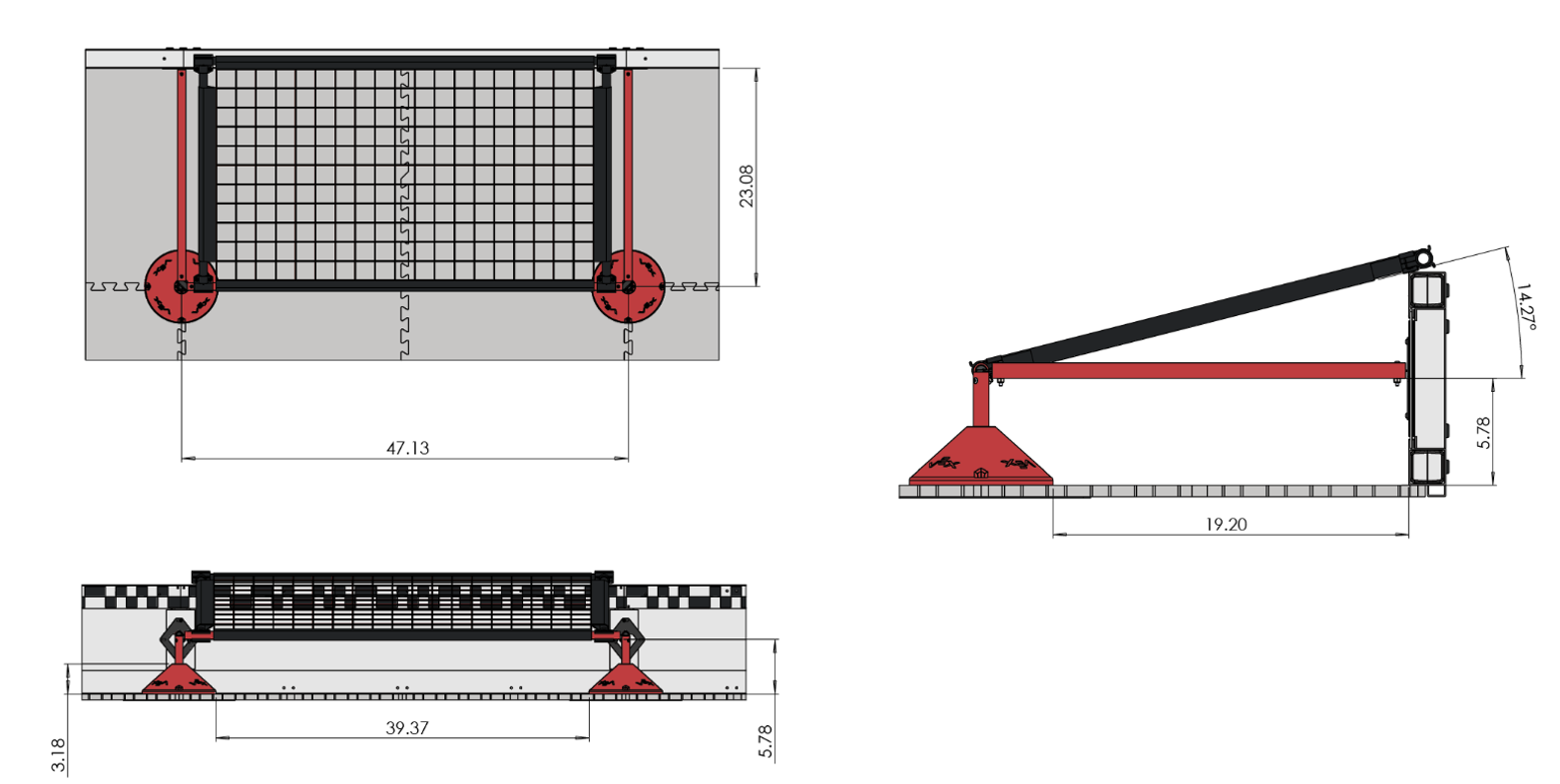
A long, cantilevered profile that can reach into the match-loading zone when the drivetrain is at a 25-degree angle relative to the match-loading pipe. This way, the robot can propel balls toward the 15” catcher robot without positioning the drivetrain inside the match-loading zone.
A dynamic component that can ‘grab’ stationary triballs — this requirement complies with this rule on intake match-loading: https://www.robotevents.com/VEXU/2023-2024/QA/1857
Allow the cantilevered structure to hinge so the intakes can drive over the middle pipe.
Actuate all rollers using only two motors.
Most importantly: Have a high (95-100%) intake success rate so match-loading can be done consistently, i.e anti-jammable.
Design process:
Requirements and Idea Generation: The design process began with determining the key design components and performance indicators that we considered critical to a successful intake mechanism. These elements were the basis for brainstorming, which included devising ways to achieve the above factors.
Solution Selection: Once ideas were conceived, they were included in a WEM and ranked according to our key design components. From the WEM, the highest-scoring design was selected. Upon selecting this design, before any CAD was made, the team determined quantifiable/measurable goals for the mechanism that could later be validated to ensure design success.
Testing and Evaluation: After the idea was selected, a prototype was designed in CAD and simulated in software, involving mathematical modelling of parameters (i.e. motor reduction requirements or beam deflection calculations). This included using collision analysis in Solidworks to determine possible sources of error before the prototyping stage. After this, the design was 3D printed and tested according to key performance indicators and iterated upon.
The idea generation phase included referencing past designs (from this year and previous) of QVEX and other teams’ intakes as inspiration. Elements that seemed to work effectively were noted and compiled into a list. From this list, mechanisms that aligned well with the key performance indicators were elaborated on and built into fully functioning ideas. Here are the plausible ideas we came up with
Idea 1: Top-roller, long-cantilevered intake actuated by two motors and a chain/sprocket system
Idea 2: Side-roller, long cantilevered intake actuated by two motors, one per side
Idea 3: Conveyor belt style intake
The generated concepts were then evaluated through a weighted evaluation matrix, which is found below. The following criteria were weighted based on their contribution to the functionality of the design.
Criteria Description
Repeatability: A measure of how often a ball successfully (i.e. not getting jammed) into the intake, expressed in a percentage
Size: A measure of the mechanism’s physical form factor. Larger is worse because it typically means a heavier and less maneuverable robot.
Effectiveness of Dynamic Component: A dynamic component (i.e., pin-jointed roller or actuated intake) can intake without human intervention. Measures reliability of the dynamic component, expressed as a percentage
Number of Motors Used: A measure of how many motors power the mechanism.
Ability to Get Over Middle Bar: Measure how difficult it is to create a design that will allow the robot to cross the middle bar
Below is the completed evaluation matrix indicating the scores for each design in their categories.
Criteria |
Weight (1-5) |
Top Roller |
Side Roller |
Conveyor |
Repeatability |
5 |
4 |
5 |
3 |
Size |
2 |
2 |
3 |
2 |
Effectiveness of Dynamic Component |
3 |
3 |
4 |
2 |
Number of Motors Used |
2 |
3 |
3 |
3 |
Ability to Get Over Middle Bar |
3 |
4 |
3 |
2 |
Total |
51 |
58 |
37 |
Based on this WEM, the team pursued the side roller.
Intake V1: Initial mathematical modelling, collision analysis, and CAD were completed in over one week for our first iteration. The below figures detail V1.

|

|

|
|
Problems:
The first problem with V1 was that the belts we used were prone to slipping and often did not mesh well with the pulleys. This led us to use idlers to guarantee contact between the belt and pulleys. However, this led to a lot of friction and caused the motors to stall out after a short time.
The second problem with V1 was that the belts would get caught in the flex-wheel material and jam the transmission. Here is an example of this:
Intake V2:
Both problems were addressed by switching to a chain+sprocket system that has less potential for slipping (and thus doesn’t need idlers, which cause unnecessary friction) and moving the transmission onto the top platform. Here is a render of the chain/sprocket system on the top of the intake.

V2 is currently being tested.
15 inch intake:
The 15-inch intake is different to account for the catcher’s space requirements. It is a top roller whose primary function is to outtake the trolls caught with the catcher.
(15 inch intake picture)
The timeline is color-coded for easier comprehension. The legend is found below.
Task Type |
Meeting |
Design Process |
CAD |
Color |
The timeline was decided upon during the first few meetings, pictured below. Any items with missing dates were at some point removed from the design. The process for this new intake begun in February.
Month |
Task |
Assigned to |
Due by |
Completed |
Dec 23 |
Intake Design Meeting |
All |
Dec 2, 2023 |
|
Roller Assembly Meeting |
All |
Dec 3, 2023 |
||
Feb 24 |
Design Modelling |
All |
Feb 16, 2024 |
Feb 22, 2024 |
Intake CAD |
All |
Feb 25, 2024 |
Feb 27, 2024 |
|
Worlds Intake Design Requirements Meeting |
All |
Feb 11, 2024 |
||
Worlds Intake Design Selection Meeting |
All |
Feb 15, 2024 |
||
Intake CAD Meeting |
All |
Feb 21, 2024 |
||
Intake CAD Meeting |
All |
Feb 27, 2024 |
||
Mar 24 |
24” Intake Assembly |
All |
Mar 1, 2024 |
Mar 6, 2024 |
Intake Assemble + Test V1 |
All |
Mar 1, 2024 |
Mar 3, 2024 |
|
Outtake Assembly |
All |
Mar 6, 2024 |
Mar 24, 2024 |
|
Intake Re-CAD + Assemble V2 |
All |
Mar 9, 2024 |
Mar 13, 2024 |
|
Intake Re-CAD + Assemble V3 |
All |
Mar 14, 2024 |
||
Final Intake Due |
All |
Mar 17, 2024 |
Mar 17, 2024 |
|
15” Outtake Complete |
Nikola |
Mar 24, 2024 |
Mar 24, 2024 |
|
24” Intake Sensor Mounted |
Will |
Mar 24, 2024 |
Mar 25, 2024 |
|
Intake Meeting |
All |
Mar 1, 2024 |
||
Intake Meeting |
All |
Mar 3, 2024 |
||
Intake Test V2 |
All |
Mar 10, 2024 |
||
Intake Test V3 |
All |
Mar 15, 2024 |

Requirements: the climber subteam is dedicated to creating a mechanism that can:
Deploy within 15–20 seconds
Fit in front of the flywheel while allowing the triballs to shoot at a ~20-degree angle.
Lift two robots, the second one lifting to the highest measurable height.
Foldable in three different places to allow for the most compact configuration.
Reach up to 30 inches on the pole while allowing the driver to drive under the 12” bar.
Have a low amount of driver control to eliminate errors.
Design process:
The team initially looked into two different mechanisms. The first drove up the pole, and the second was a four-bar. During the first semester, the team worked on making a driving mechanism that could drive up the pole. Although this mechanism worked well on an empty pole, the small black bump prevented it from climbing during a match. Additionally, the drive train was not correctly made to drive over the ground beams and could not mount the pole properly. The team then made a robotic arm that would lift two robots, combined with a clip mechanism to attach the two robots.
Multiple climb designs were considered, as the requirements were unlike any the team had encountered before. This resulted in a large preliminary brainstorming and design phase that encompassed the majority of the season. Every team member was tasked with researching and making a rough design of a system that could be used, which resulted in four major ideas.
Idea 1 - Wheels: The idea was to drive up the pole with wheels, using the moment arm of the robot to keep it up. The mechanism was placed on the robot’s side around the center of mass.

|

|
Idea 2 - Belted arm: The lower bar has a belt going from the motors to the centre joint controlling the shaft. From there, the idea was to hoist the robot up as the shaft rotated from the motors. The issue was that the arm was not kept parallel to the bar. This caused the lower half of the arm to rotate inwards instead of the upper half of the arm rotating upwards.

Idea 3 - Lower powered arm: The idea was to hoist the robot up, but the joint at the claw lacked control and twisted the wrong way. This arm would be ideal for picking up mechanisms or rotating the bottom clockwise. The claw clamping mechanism is a fully mechanical stop. When pushed into the bar, the pressure is rotated 180 degrees, pulling the four sides shut and locking on a spring-loaded stop.

|

|

|
|
Idea 4 - Four-bar arm: This idea involves rotating the arm upwards using a belt to allow the motors to remain on the drive train. The support was extended to the back of the arm to allow for a more compact design.

The generated concepts were then evaluated using a weighted evaluation matrix, which can be found below. The following criteria were weighted based on their criticality to the design’s functionality.
Strength: the motors must supply enough torque to lift 40 lbs (two robots) to the highest measurable distance in the climb. All the aluminum must be strong enough to avoid shearing and bending. This includes the parallel axis theorem.
Compact: allows the flywheel to shoot at a 20-degree angle, additionally will not protrude too far out the sides of the robot as to disrupt the same components.
Reliability: the likelihood that this will fail during the climb or break if hit by another robot.
Ease of Manufacture: In case the mechanism fails, replacing a component must be done quickly, with the ability to change between a couple of VEX games.
Aesthetic: The components add a clean look to the robot.
Below is the completed evaluation matrix indicating the scores for each design in their categories.
Criteria |
Weight |
Wheels |
Lower powered arm |
Four Bar arm |
Strength |
5 |
3 |
5 |
5 |
Compact |
5 |
5 |
2 |
5 |
Reliability |
4 |
2 |
1 |
4 |
Ease of manufacture |
3 |
5 |
2 |
1 |
Aesthetic |
2 |
1 |
4 |
3 |
Total: |
63 |
53 |
75 |
The weighted matrix shows that the four-bar arm achieves the highest score.
The wheels’ first iteration was manufactured and designed throughout
the first semester; the calculations and theoretical analysis were
conducted, ensuring that this mechanism would work in a perfect world.
Unfortunately, when the time came to integrate, the climb had to be
mounted on the far left of the robot. This caused many issues when
climbing past the black bump on the pole due to the robot’s centre of
gravity. Before the tournament, there was no time to change that, so a
second iteration was designed.
The next iteration was a robotic arm. This was designed to ‘hoist’ the
robot up; however, it lacked control over the claw. To fix this, the
third design was created by making a four-bar, allowing the robots to be
hoisted upwards.
The timeline is colour-coded for easier comprehension. The legend is found below.
Task Type |
Meeting |
Design Process |
CAD |
Colour |
The timeline, pictured below, was decided upon during the first few meetings. At some point, any items with missing dates were removed from the design.
Month |
Task |
Assigned to |
Due by |
Completed |
Oct |
Introductory Meeting |
All |
October 25 |
October 25 |
Initial Design Generation |
All |
October 25 |
October 25 |
|
Initial prototype climb |
Maya, Jaiden, Rebecca |
October 25 |
November 1 |
|
Initial Prototype climb |
Andromeda |
October 25 |
November 1 |
|
Nov |
Designing the claw mechanism |
Maya, Jaiden, Rebecca |
November 1 |
November 1 |
Sketching out a pneumatic claw |
November 1 |
November 1 |
||
Sketching out a mechanical clamp |
November 1 |
November 1 |
||
Building the designed Claw |
Maya, Jaiden, Rebecca |
November 1 |
November 1 |
|
Mechanical Clamp |
Maya, Jaiden, Rebecca |
November 1 |
November 1 |
|
Assembly of the wheel climbs |
All |
November 5 |
November 5 |
|
Final Design Selection |
All |
November 8 |
November 8 |
|
Testing the wheel climb (no robot) |
All |
November 15 |
November 15 |
|
Ratchet design |
Jaiden |
November 22 |
November 22 |
|
Final Cad completed ready for manufacturing |
Maya Jaiden Rebecca |
November 29 |
November 29 |
|
Dec |
Failure testing on prototype |
Jaiden Maya |
Dec 6 |
Dec 6 |
Jan |
CAD the sides to slim down |
Jaiden Maya Rebecca |
January 8 |
January 8 |
New climb assembled with 3D parts |
Jaiden Maya Rebecca |
January 10 |
January 12 |
|
Ratchet Remodel |
Maya |
January 13 |
January 13 |
|
Test with robot |
All |
January 14 |
January 14 |
|
Design generation for worlds climb |
All |
January 17 |
January 18 |
|
Jan | CAD first iteration of climb | All | January 30 | January 30 |
Feb |
CAD physical Stops |
Rebecca |
February 14 |
February 14 |
Manufacturing metal siding |
Xan, Rebecca |
February 16 |
February 16 |
|
New Climb assembly |
Xan Rebecca Maya Jaiden |
February 25 |
February 25 |
|
New Climb testing |
Xan Rebecca Maya Jaiden |
February 25 |
February 25 |
|
New idea generation |
All |
February 27 |
February 27 |
|
Mar |
CAD four bar v1 |
Rebecca Maya Jaiden |
March 1 |
March 1 |
CAD robot - climb mount |
Xan |
March 1 |
March 4 |
|
Manufacturing |
All |
March 4 |
March 4 |
|
Assembly |
All |
March 5 |
March 5 |
|
Testing |
All |
March 11 |
March 11 |
This section introduces the software subsystems, their goals, and their timeline.
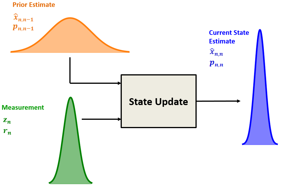
Requirements: The robot localization subteam is dedicated to creating software that can:
Accurately track robot location within the field
Process readings from several sensors around the robot
UKF: The localization engine centers around an unscented Kalman filter (UKF). This algorithm allows us to combine several sensor readings, such as encoder measurements, Lidar measurements, IMU measurements, and vision measurements, to accurately locate the robot on the field.
3-Wheel Odometry: One common way to localize a robot on the field is to use three non-driven omni wheels that roll along the ground to detect the robot’s movement and rotation. The wheels have a highly accurate encoder that detects their rotation, allowing the system to be precise.
Drive Encoder + IMU Odometry: Another way we could localize the robot is to keep it simple, use the encoders in the drive motors as a replacement for the left and right wheels in three-wheel odometry, and use the IMU to estimate the robot’s angle.
The generated concepts were then evaluated through a weighted evaluation matrix found below. The following criteria were weighted based on their criticality to the functionality of the design. The values were used to prioritize the order in which these algorithms should be developed
Accuracy: The estimated positional accuracy of the localization system. This is the most crucial factor of the localization system, as increased accuracy will provide superior control during the autonomous period.
Resilience: The localization system’s resilience to external factors that could cause inaccuracy. This is slightly less important as the robot should not be affected by unexpected factors during the autonomous period.
Ease of Implementation: The ease of implementation should be considered when deciding what localization system to test first to ensure the team has a reliable localization system for earlier competitions. This will be weighted heavily as it is likely that several of these systems will be developed, so we should develop the easiest first to evaluate their performance.
Experience: The experience the team members have using the system. If we are more experienced using the system, it will be easier to develop and debug, leading to a higher likelihood of success.
Innovation: Although this is considered less critical, the team wants to create memorable solutions and try new things that deviate from the norm, which may be beneficial.
Below is the completed evaluation matrix indicating the scores for each design in their categories.
Criteria |
Weight |
UKF |
3 Wheel Odometry |
Drive encoder + IMU Odometry |
Accuracy |
5 |
5 |
4 |
2 |
Resilience |
2 |
5 |
3 |
2 |
Ease of Implementation |
5 |
1 |
3 |
5 |
Experience |
2 |
1 |
5 |
4 |
Innovation |
1 |
4 |
1 |
1 |
Total |
46 |
52 |
40 |
The evaluation matrix shows that it makes sense to invest time into 3 Wheel Odometry and Drive Encoder + IMU Odometry, as these are relatively easy to implement. After we complete these, we can work on UKF localization with several sensors mounted on the robots.
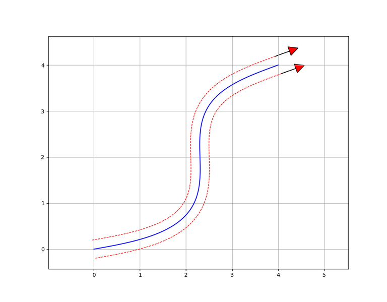
Requirements: the motion controllers subteam is dedicated to creating software that can:
Control the drivetrain of the robot using motion algorithms
Accurately and efficiently get from one point to another
Subprojects:
Ramsete controller: Allows for feedback control when following a pre-generated path.
PID algorithms: Can be used to control individual mechanisms, such as the drivetrain and the entire robot during the autonomous period.
Pure Pursuit: Another method which allows the robot to follow a curve smoothly.
The generated concepts were then evaluated through a weighted evaluation matrix. The following criteria were weighted based on their criticality to the robot’s functionality. These numbers were then used to decide which way
Flexibility: Some motion algorithms may better suit complex situations like curves and long paths.
Ease of Implementation: It makes sense to invest time into easier motion algorithms to ensure good performance during early competition.
Speed: How fast the algorithm can allow the robot to traverse the field.
Accuracy: How consistently the robot can traverse the field and end at the same position.
Below is the completed evaluation matrix indicating the scores for each design in their categories.
Criteria |
Weight |
PID Algorithms |
Ramsete Controller |
Pure Pursuit |
Flexibility |
2 |
2 |
5 |
4 |
Ease of Implementation |
4 |
5 |
1 |
2 |
Speed |
3 |
2 |
5 |
5 |
Accuracy |
4 |
3 |
5 |
4 |
42 |
49 |
47 |
This shows that the Ramsete path-following algorithm and the pure pursuit controller are better path-following solutions than the PID controller.
Requirements: The subsystem controllers team is dedicated to programming mechanisms of a robot by enabling individual hardware components to operate as a unit; the team has various responsibilities to uphold:
Bringing several components together to execute one or more actions as a unit
Similarly, related units in the robot must be smoothly integrated to operate effectively
Implementing ways to process inputs from sensors, control actuation, and communication
Streamline development of autonomous routines by developing elegant and powerful solutions, expanding the realm of possibilities
Design practical and flexible control schemes that are easy to grasp and grant freedom to drivers
Fully encapsulate and remain faithful to hardware designs
Design process:
The subsystem controllers team works closely with hardware teams to properly grasp the intricacies and function of their designs before expressing them in code. Our idea generation is concerned with breaking down what a group of components (a “unit” or “subsystem”) may be doing at any given moment and breaking them down into a concise set of states that the subsystem may transition between, the relation between these states can be expressed in a state-transition diagram that allows the function of each unit to be expressed as a finite-state machine.
Example of a state-transition diagram for the climber’s subsystem controller:
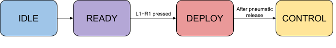
These states are the basis of each subsystem controller’s design. The behaviour and interaction of components (e.g. motors, pneumatics, etc.) within each state are then expressed in code, with actuation conditions and execution determined through subroutines based on controller input, data from sensors, or inter-subsystem/inter-robot communications. Subsystem states are determined on a case-by-case basis. They are entirely dependent on the components/mechanisms being encapsulated within it, except for an “idle” state in which the subsystem is not in use and, therefore, does not use hardware.
This systematic method allows subteam members to create solutions that match our selection criterion (listed below under “Solution Selection”). These solutions are typically easily adaptable to changes caused by updated designs or error fixes. Solutions are programmed in Rust using vex-rt, our Rust runtime for Vex V5 components.
Subsystem controllers are designed with adaptability and must be susceptible to change to match the dynamic nature of the whole team’s work and design processes. Rather than a strict evaluation method, we use criteria to determine whether a solution fits our needs. The subsystem controller will be constantly evaluated under this criterion, and changes will be made as necessary.
Criterion:
The subsystem controller must completely encapsulate the hardware design. Ensure complete functionality is available within specified constraints (e.g. expected abilities, performance, range of motion, applications).
Multiple units/subsystems expected to operate simultaneously must not interfere with each other or result in unintended behaviour. Examples include multiple units attempting to use a shared component, multiple subsystem controllers using the same input from a V5 controller (e.g., the same button performing multiple actions), or unintended actuation during autonomous routines.
Conditions (data from sensors, states, etc.) must be met before components are actuated to prevent unexpected behaviour.
Control schemes are practical and easy for the drivers to use and understand (based on feedback from drivers)
The subsystem controller must be accessible enough for programming autonomous routines (based on feedback from autonomous programmers, criterion 1 must be satisfied)
The solution will be used several times during preparation. This may be in programming autonomous routines, practicing for competitions, or testing hardware or other software. The subsystem controllers subteam has many opportunities to receive feedback on the solutions to each unit from those involved in these processes, and changes are made as necessary to ensure our finalized solutions not only meet the expectations for what our robots are capable of but also streamline the preparations above and bolster our performances at each event.
Following QRC- in which our performance didn’t meet expectations- we looked at what went wrong and how we could refine our solutions. Due to a majority of issues being mechanical and the small number of changes being made before our next competition, the changes we looked into for the individual solutions were quite small:
New subsystem controller- Controlling the new flaps/walls on the robot’s side.
Adjust intake/puncher controllers - If the other team shot a triball into the range of the intake’s sensors, it could interrupt our autonomous routine (failing to meet the second criterion of our solution evaluation). The intake wasn’t fully consistent and could get jammed, so behaviours were adjusted to detect if a triball was stuck in the intake and expel it.
Autonomous programming difficulty
Overall, the subsystem controllers subteam couldn’t properly conduct tests for various scenarios that may happen in an actual match. We fell short in some areas and had some oversights. As a result, our evaluation criterion was updated to include the 5th criterion and an amendment to the 2nd criterion to include “unintended actuation during autonomous routines.”
During our competition in West Virginia, we saw massive success since we had a fantastic performance and managed to qualify for worlds. However, we still had lots to do due to the larger number of teams compared to QRC; we had many more opportunities to observe our robots in real competition to evaluate the overall performance and look for issues. One of our first issues is how our code is structured; the autonomous programmers expressed concerns with our code regarding several inefficiencies and points of confusion that made their job more difficult, our solution being an overhaul of the code structure to resolve these problems. Restructuring our code was a high-priority task since our final subsystem controllers for our robots at worlds would be built upon them.
The subsystem controllers would also undergo massive changes since the new robots in production are massively different from the previous iterations in QRC and West Virginia. New components such as robot communications and our powerful firmware additions mean that we could use new forms of input and process them at faster rates than before. Because of this, the subteam is working on sophisticated algorithms that allow for more advanced subroutines that are more powerful, reduce the pressure on drivers, and streamline the job of autonomous programmers.
The timeline is colour-coded for easier comprehension. The legend is found below.
Task Type |
Meeting |
Solution Programming |
Documentation |
Colour |
Month |
Task |
Assigned to |
Due by |
Completed |
Oct |
Introduction |
All |
15-Oct-23 |
15-Oct-23 |
Initial Setup |
All |
16-Oct-23 |
16-Oct-23 |
|
General meeting |
All |
27-Oct-23 |
27-Oct-23 |
|
Nov |
Drivetrain controller demo |
All |
07-Nov-23 |
07-Nov-23 |
Explaining subsystem architecture |
All |
17-Nov-23 |
17-Nov-23 |
|
Delegation of tasks and work session |
All |
24-Nov-23 |
24-Nov-23 |
|
Intake controller |
Ruby Wang |
13-Jan-23 |
08-Jan-23 |
|
Climber controller |
Kashan Rauf |
13-Jan-23 |
05-Jan-23 |
|
Puncher controller |
Ryan Jacobson |
13-Jan-23 |
11-Jan-23 |
|
Dec |
Work session |
All |
01-Dec-23 |
01-Dec-23 |
Work session |
All |
08-Dec-23 |
08-Dec-23 |
|
Jan |
Progress update |
All |
08-Jan-24 |
08-Jan-24 |
Work session |
All |
09-Jan-24 |
09-Jan-24 |
|
Intake documentation |
Ruby Wang, Calvin Birch |
13-Jan-24 |
11-Jan-24 |
|
Climber documentation |
Kashan Rauf, Calvin Birch |
13-Jan-24 |
12-Jan-24 |
|
Puncher documentation |
Ryan Jacobson, Calvin Birch |
13-Jan-24 |
12-Jan-24 |
|
Progress update, next steps following QRC |
All |
28-Jan-24 |
28-Jan-24 |
|
Feb |
Refining intake controller |
Ruby Wang |
14-Feb-24 |
11-Feb-24 |
Refining puncher controller |
Ryan Jacobson |
14-Feb-24 |
9-Feb-24 |
|
Implementing intake jam detection/handling |
Calvin Birch, Kashan Rauf |
14-Feb-24 |
14-Feb-24 |
|
Work session |
All |
10-Feb-24 |
10-Feb-24 |
|
Next steps following the qualification |
All |
29-Feb-24 |
29-Feb-24 |
|
Mar |
Work session |
All |
06-Mar-24 |
06-Mar-24 |
Mar | Code restructuring | All | 09-Mar-24 | 09-Mar-24 |
Worlds drivetrain controller |
18-Mar-24 |
|||
Worlds climber controller |
Kashan Rauf |
18-Mar-24 |
||
Worlds intake controller |
18-Mar-24 |
|||
Robot communication controller |
18-Mar-24 |
|||
Catcher controller |
18-Mar-24 |
|||
Documentation updates for all controllers |
All |
18-Mar-24 |
This team aims to develop all the software running on the custom PCBs. During the first part of the season, while we are designing and getting the boards manufactured, we develop several valuable tools and features of the common library that will help streamline the development of the firmware. These tools included but were not limited to a common timer system and improvements to our inter-board communication system.
Once we have the boards designed, the team’s focus will shift to planning. Since the boards take a long time to manufacture, we can design and plan most of the firmware before we have the boards in hand. This includes creating detailed descriptions of all the tasks the board needs to perform, software requirements we must design, and testing plans. We can develop code and test it in simulations for some parts of the projects.
Developing the software for these boards requires a slightly different design process than our other software projects. Since most of the testing cannot happen until we have the PCBs in hand, and once we have them, they must be given (with firmware) to the other software teams as soon as possible, we have a very short testing period. That means our design process puts a lot more weight on the brainstorming and planning stages to reduce the time needed to debug and test in the later steps.
Requirements:
Interface with all sensors on the Odometry board
Manage communications between the Jetson Nano and all other devices
Synchronize and timestamp the data produced by 4 cameras
Develop a robust communication system between the V5 and all coprocessors
Problem Identification: We create and analyze the requirements for a specific project. In this step, we define the scope of the project, its goals, and exactly what data it will handle. By tightly defining each of these factors, this step allows us to easily compare a proposed result back to the project in later steps to determine viability. In this step, we will also define the decision matrix, which will be used for solution selection.
Prototype Solutions: Based on our requirements and scope, as defined in the previous step, the assignee will brainstorm possible solutions and create a detailed plan for exactly how this code will work and interact with the surrounding software.
Solution Selection: The assignees will present their solution proposals to the rest of the subteam. In this meeting, the rest of the subteam will look for parts of the problem that might have been neglected, possible edge cases, and other failure points in the proposals. From this, the entire subteam will fill in the decision matrix and determine the best solution.
Test Definitions: Once a solution has been selected, the assignee will develop a test suite, which will be used to confirm the functionality of aspects of their solution. This test suite should be able to be run on their code before we receive the boards and thus will include unit tests on portions of code and simulations (where possible).
Develop: In this step, we write the code as proposed.
Evaluate: Once the code has been written, we complete the test suite, evaluate the performance and perform code reviews. If any problems were found, or possible improvements could be made we revise the solution proposal and return to the development step.
Hardware Integration: This step takes place once we have the PCBs. In this step, we run all projects on the hardware, testing all necessary features and ensuring the solution matches our requirements. Any issues found in this step are documented, and the assignee will return to the development step to continue iterating on the problem.
This section introduces the electrical subsystems, their goals, and their timeline.
Requirements: the Jetson Nano Carrier Board shall:
Provide power to the Jetson Nano in accordance with its requriements
Provide the ability for the Jetson Nano to communicate with the main robot communication bus
Provide the ability for the Jetson Nano to take input from the four cameras connected to the camera board
Provide I/O capabilities for a cooling fan and other general-purpose I/O
Power supply: The power supply circuitry takes input from two sources: an external, dedicated rechargeable battery and the power lines from the V5 robot brain. If both are available, it chooses the external battery. The chosen input source is regulated down to 5 V. The power supply circuitry can supply up to 6 A of current.
Robot communications: The robot comms circuitry provides an interface between the Jetson Nano and the RS-485 main communication bus between the V5 robot brain and custom peripherals. Due to the communications bus’s timing requirements, it is handled by a dedicated microcontroller, which communicates separately with the Jetson Nano.
Camera communication: The camera comms circuitry allows the camera board to communicate with the Jetson Nano.
General purpose I/O: Several extra I/O pins from the Jetson Nano are broken out to connect arbitrary accessories. This includes a dedicated port for connecting a cooling fan controlled by the Jetson Nano.
Requirements: the Camera Board shall:
Provide connections for four MIPI-CSI cameras to connect to the Jetson Carrier Board, including translating logic levels where needed
Allow the I2C communications with the camera to be multipliexed between several I2C busses from the Jetson Nano and a dedicated microcontroller on the Camera Board
Have a dedicated bus for providing timestamp information to the Jetson Carrier Board and the Jetson Nano
Microcontroller: The dedicated microcontroller has 5 I2C busses, one for each camera and one connected to the Jetson Nano. Several of the I2C busses are connected through digital switches which permit the busses to be multiplexed between the different hosts and peripherals. This is necessary as all four cameras have the same I2C addresses.
Requirements: the Odometry Processing Board Mark IV shall:
Communicate with the main robot communications bus
Receive power from the V5 robot brain via the main communications
Incorporate 2 intertial measurement units (IMUs)
Support connections for 4 quadrature encoders and 2 LiDAR sensors
Robot communications: The robot comms circuitry provides an interface between the Odom Board and the RS-485 main communication bus between the V5 robot brain and custom peripherals. It is directly connected to the main microcontroller on the board, which is an RP2040, a dual-core Cortex-M0+ microcontroller.
Power supply: the power supply circuitry provides at least 2A power at 5V, regulated down from the main robot power bus. The same buck regulator circuit is used as on the Jetson Carrier board.
IMUs: two IMUs are connected via I2C bus. The IMUs are placed closely together to ensure their measurements reflect effectively the same physical motion, so that noise can be removed.
External sensors: The LiDAR sensors, which are RPLidar A1M8 models, are connected to PWM outputs and UART connectors so that the sensor may be connected in accordance with its datasheet. For encoders, each connector includes A and B quadrature inputs as well as an index pin which allows for absolute positions synchronization.
Author: Maxim Pletnev
Participants: Callum Warner, Oliver Lynn, Joshua Paddock, Xan Giuliani,
Maxim Pletnev, David Colaco
Decided to use a skid steer drivetrain, since it has greater pushing power.
Created an outline for designing and building the drivetrains.
Production Outline:
Oct 22th meeting
Oct 22nd - Nov 5th
Nov 21st
Dec 5th
Author: Maxim Pletnev
Participants: Callum Warner, Oliver Lynn, Joshua Paddock, Xan Giuliani,
Maxim Pletnev, Patrick Shu, David Colaco
Minutes:
To do:
Author: Maxim Pletnev
Participants: Callum Warner, Oliver Lynn, Joshua Paddock, Xan Giuliani,
Maxim Pletnev, Patrick Shu, David Colaco
Minutes from today’s meeting:
decided to have two meetings next week (thursday and sunday)
Author: Maxim Pletnev
Participants: Callum Warner, Oliver Lynn, Joshua Paddock, Xan Giuliani,
Maxim Pletnev, Patrick Shu, David Colaco
Author: Maxim Pletnev
Participants: Oliver Lynn, Joshua Paddock, Xan Giuliani, Maxim Pletnev,
David Colaco
Author: Maxim Pletnev
Participants: Oliver Lynn, Joshua Paddock, Xan Giuliani, Maxim Pletnev,
Patrick Shu, David Colaco
Author: Maxim Pletnev
Participants: Callum Warner, Oliver Lynn, Xan Giuliani, Maxim Pletnev,
David Colaco
Meeting consisted of determining design features which required updating for the new design, and features which need to be retrofitted to the current drivetrains for the upcoming competition in February.
The original design had a few flaws, but the most fatal was the power output gears(the gears coming out of the combination gearbox) had a tendency to hollow out the square shafts. A simple addition in the field was to add metal brackets to the gears which would transmit the torque instead.
The second flaw we found was that the motor mounts had a collection
of small mistakes, making them unreliable and bulky. The mounts were
also printed on an untuned printer which was under-extruding filament
causing a mechanical failure before our last match.
both of these issues have been resolved in CAD and just require the
parts to be re-printed.
For the updated drivetrains we decided to move the motors to the rear
of the drivetrain to give more space to mount an intake and catching
mechanism. We also adjusted the climbing wedge angle on the front and
back of the bot. Finally, to make the whole drivetrain frame more
useable as a robotics platform we fixed some of the hole spacing to be
on a ½” square grid. A locating feature was added to the bottom of the
drivetrain and an area was cutout to eliminate a deadzone in the barrier
climb.
These design updates were made to a new version of the CAD.
This time the team got permission to use the manufacturing shop in the university. A couple of trained team members will program the parts to be cnc’d on a water-jet cutter, while some pieces will need to be milled.
Author: Maxim Pletnev
Participants: Callum Warner, Oliver Lynn, Xan Giuliani, Maxim Pletnev,
David Colaco
As some of the team is getting busy in the machine shop we added some more mods to the old drivetrains. A moving plow was added to the backs of both bots, the plow can pivot upward to allow for the barrier climb. Both bots had their “walls” entirely rebuild, now they pivot out from the side instead of the top. This allowed us to make them longer and taller. Now they effectively act like additional plows, allowing the driver to effectively move triballs over the barrier.
Author: Patrick Shu
Participants: Arman Jivraj, Xan Giuliani, Peter Tennant, Tayte
Chennette, Will Steedman, David Colaco
This includes:
All shooter prototype designs have some common components that allow it to shoot. Every shooter must have a “basket” to hold the triball in place, a method of accelerating a triball to a high velocity, as well as a frame to hold gears/motors/components.
The shooter team was split into 3 teams for the prototyping phase, to work on the 3 prototypes mentioned above. The teams completed their initial drawings to visualize the core components (gears, triball position, and motor) of their respective mechanism.
Here are initial drawings done for the rotational puncher:
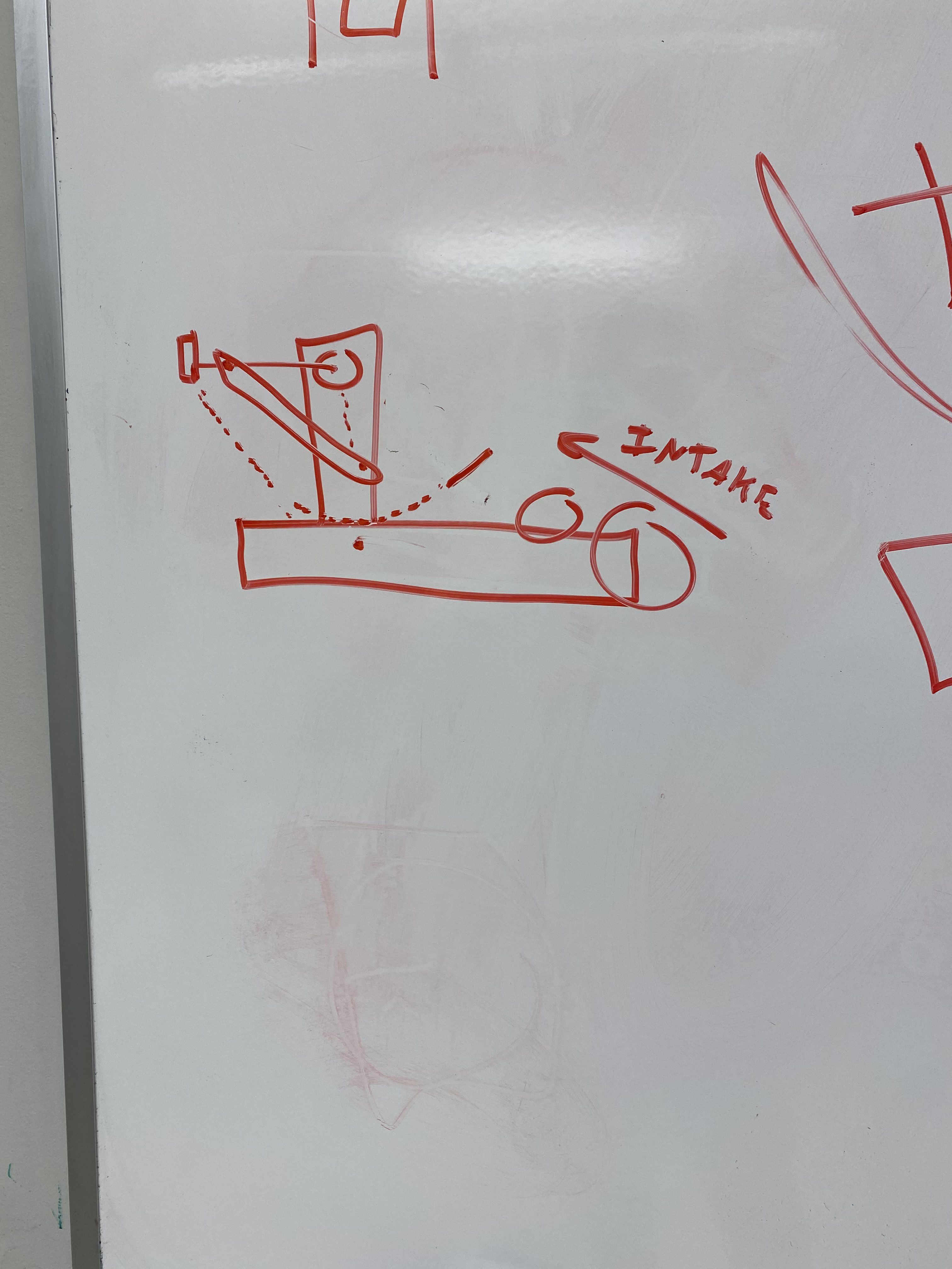 |
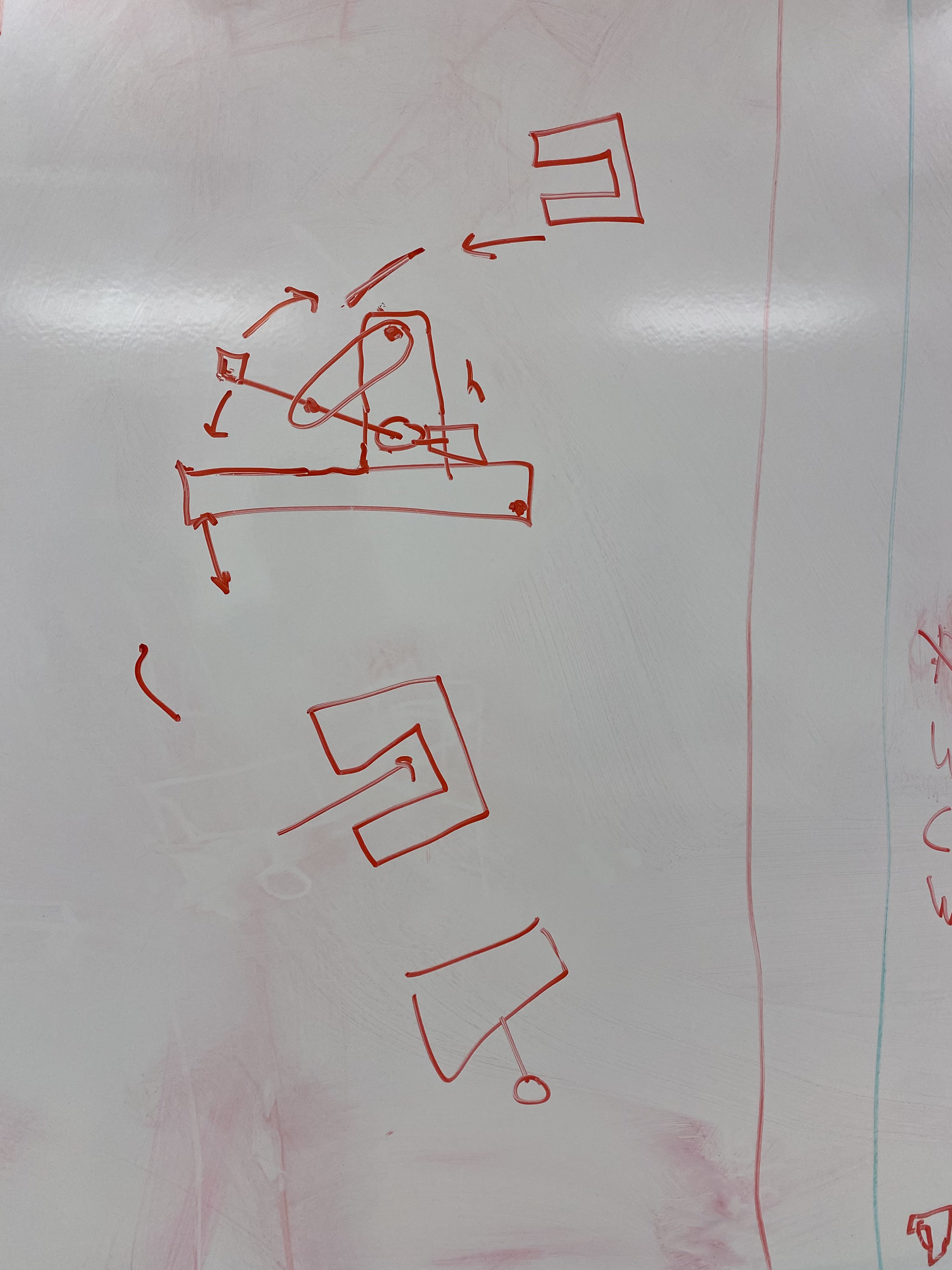 |
Author: Patrick Shu
Participants: Arman Jivraj, Xan Giuliani, Peter Tennant, Tayte
Chennette, Will Steedman, David Colaco
Patrick introduced the slip gear mechanism, which a key component of any shooter mechanism that uses elastic potential energy to transfer into a large kinetic energy into the triball.
Using an elastic system is much more effective than using traditional methods of mechanized movement, such as a motor. Motors do not nearly provide the necessary acceleration to achieve a large force over a short period of time. Past vex challenges often utilize a shooting mechanism, in which an elastic-driven mechanism is used widely.
The video below shows one of our prototypes build by another team. This showcases the slip gear mechanism in action.
https://www.youtube.com/shorts/OHr9dz5poX0
The prototyping teams devised a loose plan for the next 2 weeks to create a CAD prototype of their mechanism.
Author: Patrick Shu
Participants: Arman Jivraj, Xan Giuliani, Peter Tennant, Tayte
Chennette, Will Steedman, David Colaco
All teams finished their prototypes over the course of the week, and parts were printed to create physical prototypes to test. The plan for the next 2 weeks is to cad a full assembly of the shooter prototypes. Rotational puncher team was dissolved to accelerate the designs of the other 2 teams.
Catapult team modified last year’s catapult by mounting a new basket to the catapult arm. Here is a cad model of last year’s design.

|

|

|
The basket was designed to comfortable hold the triball but prevent it from spinning inside of it. The walls ensure a straight trajectory when flung. Here is a video of it in action:
Linear puncher team caded and printed a rough prototype of the mechanism. Here is a cad of the initial design:
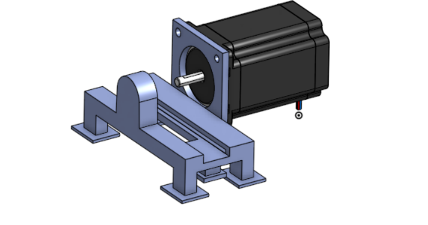
The slip gear and rack are not shown. Here is a video of it working:
The plan for the next week is to Cad and assemble a puncher that utilizes a vex motor as well as increase the form factor to be able to shoot a triball.
Rotational puncher team caded a prototype, but it was lost when one of the team members got locked out of their onshape account, as it wasn’t shared. It was also determined that both of the other teams needed some extra hands for the next few weeks, as they design, manufacture, and test their final prototypes for the first competition.
Author: Patrick Shu
Participants: Arman Jivraj, Xan Giuliani, Peter Tennant, Tayte
Chennette, Will Steedman, David Colaco
The teams have finished the prototyping phase of the shooter mechanism. The Rotational puncher team finished a rough cad, but unfortunately that was lost to technical difficulties. It was then decided that the rotational puncher team is to be dissolved and absorbed into the other 2 teams.
The focus of the next 2 weeks is to have a full cad of the shooting mechanism in an assembly file so we can spend the next 2 weeks after that manufacturing it and solving minor issues.
This week, Patrick introduced a new dimension to consider when designing a shooter mechanism, parabolic trajectory patterns. Since our strategy relies on the shooter shooting into a catcher, the ball must be shot in such a way where the triball can be caught at any distance up to 12 ft. Here is a figure to explain what this is:
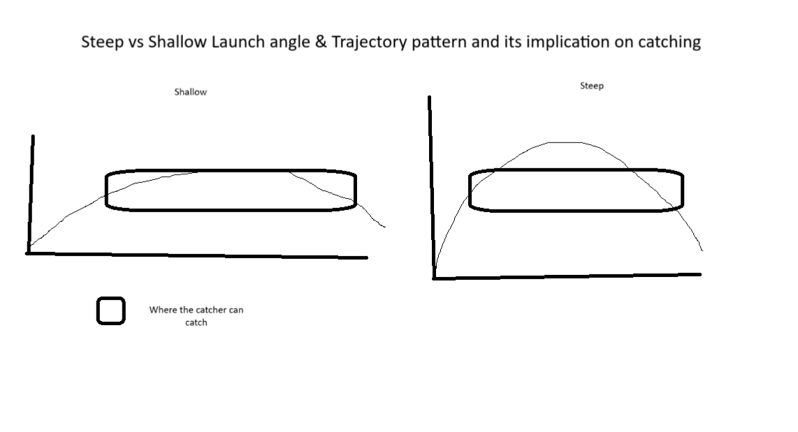
As you can see, a shallow parabolic trajectory pattern is more desirable for our strategy. Both designs will focus on making their trajectory pattern more shallow but also cover the required 12 ft.
Catapult team will base their new design off last year’s design, but adapting it to be better, smaller, faster, and more robust. Here is a list of areas for improvement with the team’s solution to them.
| Issues with old design | Proposed solution for new design |
| Slip Gear not slipping at proper angle | Manufacture new slip gear with correct amount of teeth |
| Shot angle is not sharp enough; trajectory pattern is too sharp | Increase shot angle by 15 degrees |
| Frame is bent from catapult arm slamming against it | Design and mount a low-infil tpu absorption block to take the blow |
| Catapult arm is too long and bulky | Switch from 4.3mm to 2.3mm aluminum plate for the arm, and shorten arm. |
| Catapult arm shaft bent | Switch from screw joint to 8mm shaft with imbedded bearings in the half-gear |
| Basket 1.0 walls are preventing a clean exit, too bulky, and not enough mounting holes | Reduce footprint, thin walls, and take out the front/part of the side walls. Add more mounting holes |
| Suboptimal gear reduction | Direction drive slip gear with a larger half gear instead of gearing down to a slip gear. |
In addition, the team started to cad the final design. Here are some of the parts that were caded:
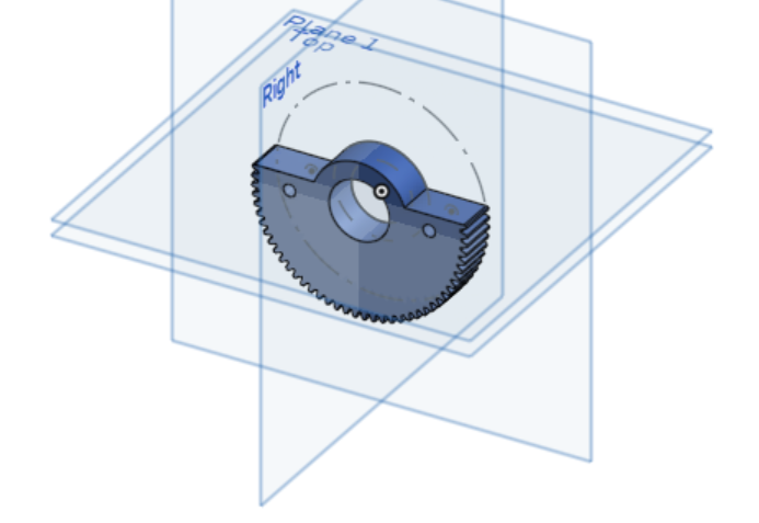 |
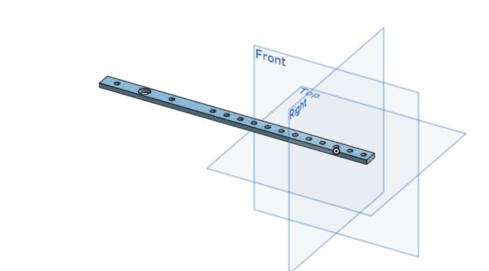 |
The plan for the next week is to finish cading the rest of the catapult, so we can start assembly.
Puncher team does not have a physical design from previous years, so the team will have to do a bit of research into how punchers are done in vex.
https://www.youtube.com/shorts/OHr9dz5poX0
This is a typical vex linear puncher. One of the areas of improvement that the team saw was that the puncher is very very long, because if you had a puncher with that length (in the video) with a triball sitting in front of it (it being 7in in diameter), the puncher would far exceed the size constraints of the 15” robot. Therefore, it is much more space efficient to have the puncher bold (the thing hitting the triball) to be at the back of the rack, and that the rack & slip gear be below the triball’s position, instead of behind. The team spent a lot of time this week cading up their design, and this is what they came up with:
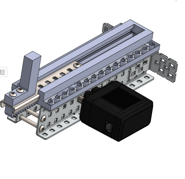
2 c channels form the frame, with 2 3d printed tracks, which perfectly houses the shape of the vex rail. A 3d printed rack is attached to it, which meshes with a slip gear directly driven by a 100 rpm motor.
The next steps for the team is to print out the parts and perform a preliminary test to see if their apparatus is successful.
Author: Patrick Shu
Participants: Arman Jivraj, Xan Giuliani, Peter Tennant, Tayte
Chennette, Will Steedman, David Colaco
The teams this week continued to make progress on their designs.
Catapult team continued making progress on the cad, as well as the team starting to assemble the frame of the catapult. Here are some more parts & the full cad design of the catapult:
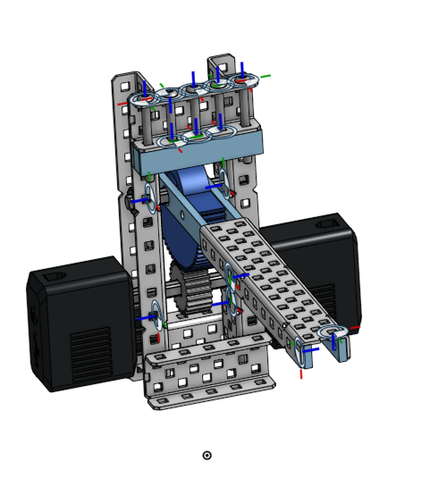 |
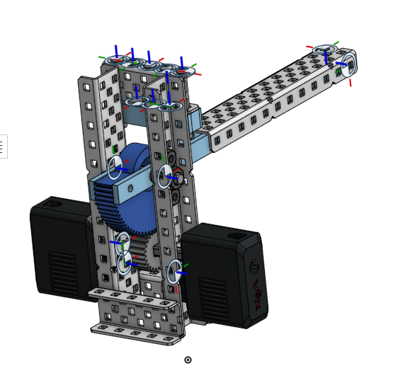 |
However, it is noted that the basket has not been completed yet, but is almost finished. Note that the bearings are not shown, but are imbedded in the half gear, clamped by the catapult arm, which swivels on a thick 8mm shaft. A tpu block sits above the catapult arm. The next steps for the team is to finish and print the new basket, as well as manufacture the arms, sand down teeth on the slip gear, and assemble everything together.
Puncher team was hard at work this week assembling a working puncher, and completed their first test.
This is the aftermath of our first test
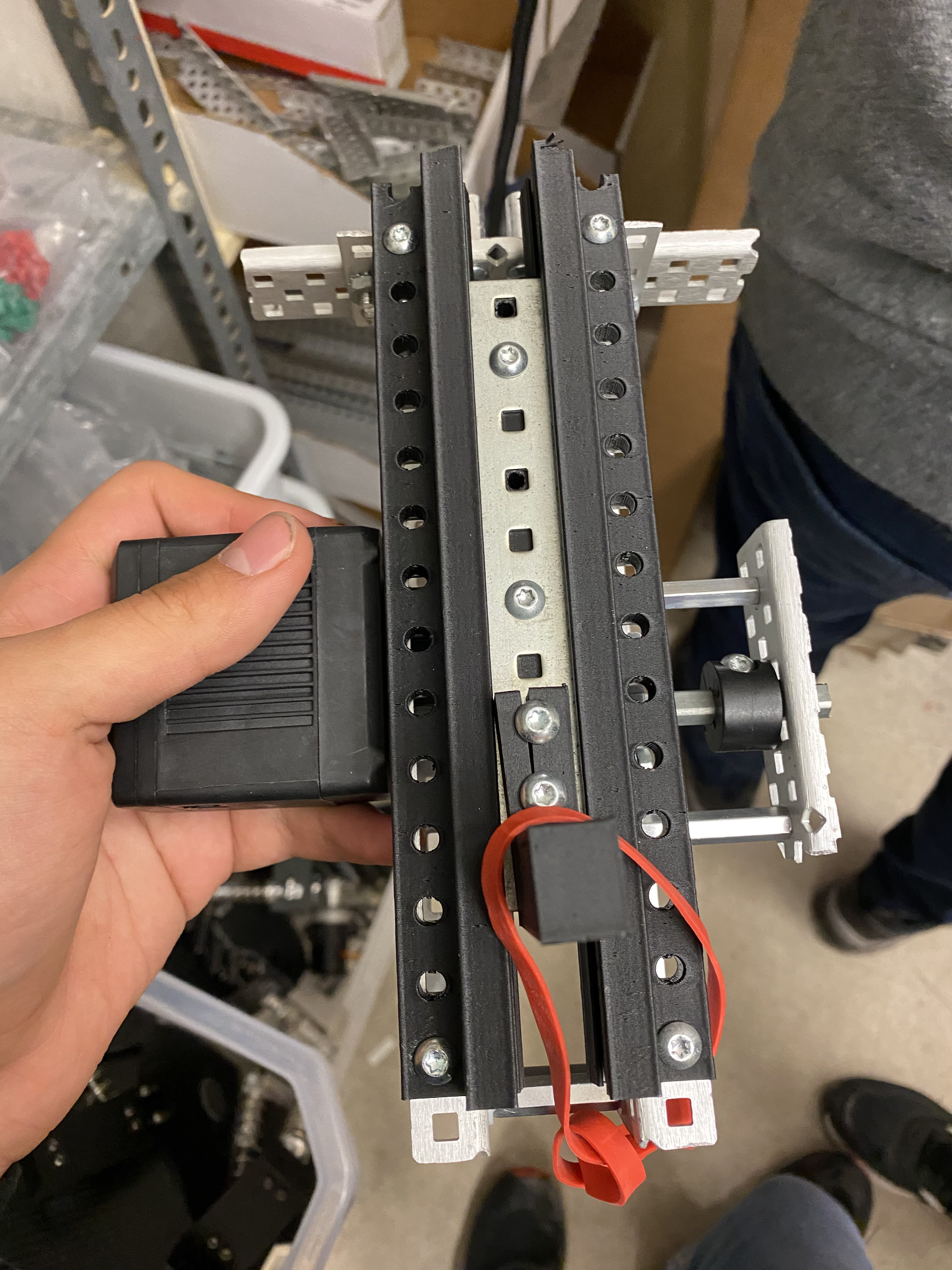
The team decided to fix the issue by using a stretched out flex wheel to soften the impact of the rail on the frame. Here is a reprinted version:
Unfortunately, the motor does not have enough torque to pull back the necessary amount of bands that are required to launch the triball, so the team will focus on a reduction next week, as well as cad/ manufacture the bolt that will eventually contact the triball.
Author: Patrick Shu
Participants: Xan Giuliani, Peter Tennant, Tayte Chennette, Will
Steedman, David Colaco
The teams are near completion of their final designs. A decision will be made at the end of this log, as well as an explanation.
Basket 2.0 was caded and printed. The catapult is more or less fully assembled, testing will begin next week if it is chosen as our shooting mechanism for 1st comp. Here is a picture of the basket 2.0 cad:
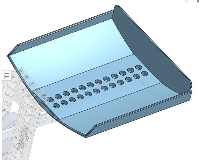
A band mount was created with standoffs from the frame, attached to standoffs underneath the basket attached to the arm.
The linear puncher is now fully designed and manufactured minus the basket in which it will sit in. The flex wheel has been replaced by a low-infil tpu block. This is an improvement on the current flex wheel as the tpu block will have a much longer lifespan. The new gear ratio of 1:2.3 was also added, which allows it to pull back more bands. In addition, the L-bracket and bolt was manufactured as well. Here is a video of it in action:
As you can see, the puncher has no problem shooting the triball 12ft. The next steps for the puncher team is to modify the catapult basket to fit a puncher.
Finally, the team, including the team lead, VP Tech, and President decided that a puncher will be used for the first comp, primarily because it is easier to fit an intake into, as well as that the puncher’s parabolic trajectory pattern is easier to tune than a catapult (as it is much easier to change the launch angle of a puncher than a catapult).
Author: Patrick Shu
Participants: Michael Cassidy, Tayte Chennette
The Basket 2.0 was modified to have a slot for the puncher bolt to shoot through, as well as the back plate being curved to fit the triball perfectly. Mount holes were appropriately placed for mounting on the rail.
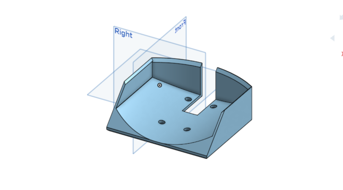
Author: Michael Cassidy
Participants: Michael Cassidy, Peter Tennant, Will Steedman, Patrick
Shu
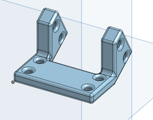 |
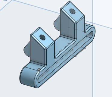 |
We printed this while working on the intake and assembled it once the prints were completed.
Author: Patrick Shu
Participants: Xan Giuliani, Peter Tennant, Will Steedman, Patrick
Shu
After QRC, the team identified aspects of the puncher which needs to be improved both in the current design, and the future worlds design. These are some of the improvements that were identified:
All of the current puncher issues stems from the basket, and not the punching mechanism itself.
The team also identified different ways to combat these basket issues with the following basket fixes:
Author: Patrick Shu
Participants: Xan Giuliani, Peter Tennant, Will Steedman
This past week the team experimented with a large variation in basket modifications and additions. Here is a cad of the new basket:
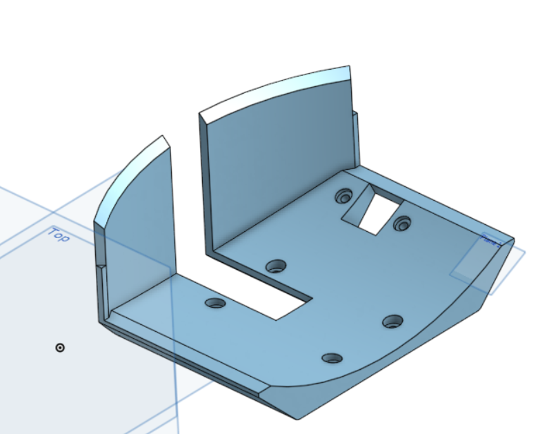
This basket incorporates many improvements identified in last week’s meeting, including removing the walls, moving the basket half an inch back, and making the back wall a bit higher.
In addition, a mount for the distance sensor was proposed by the programmers, for a more reliable and compact solution, instead of mounting the sensor outside the basket.
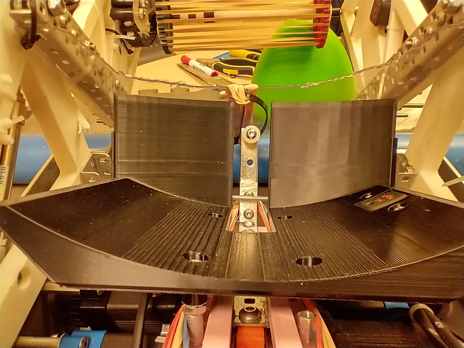
This basket proved to be a great upgrade over the previous design, but it still suffers from high friction between the triball and the basket. The triball is able to correct itself a lot better without the side walls impeding it. In addition, moving the basket back and the back wall higher allows the triball to enter the basket with greater momentum, raising the chance of the triball correcting itself. The success rate of this basket rose from 30% (the old one) to a promising 70%, over 25 triballs.
The team will spend the next week fixing the high friction.
Author: Patrick Shu
Participants: Xan Giuliani, Peter Tennant, Will Steedman
This week, the team fixed the friction issues between the triball and the basket by adding a low-friction medium in between them. The triball itself is quite rough, it does not slide very well and prefers to roll. The 3d printed material also has a lot of ridges and contours from the layer lines. Therefore, a thin material which is smooth is an ideal solution.
One of the members proposed to use stickers, which both is an easy application and boasts quite a low friction coefficient. It does not add much material which would change the dimensions of how the triball is hit.
This basket improved its old 70% success rate to a very promising 95% success rate over 25 triballs. These stickers make a huge difference to how quickly and how effectively the basket can manipulate the triball. However, after lots of repeat testing, the stickers show that it can wear out over time and dust and other particles can pepper the surface. Over a long period of time, the stickers eventually lose its low friction capability. Therefore, a more long-term solution will need to be designed. Ideally, it is a passive system and not an active system which requires a motor or pneumatics.
Author: Patrick Shu
Participants: Xan Giuliani, Peter Tennant, Will Steedman
This week the team replaced the stickers with a 1/16 polycarbonate sheet. It is about the same material as stickers and it provides the same low-friction contact surface.
Counter-sunk screws are flush against the poly, and the basket is spaced down 1/16 to compensate for the additional 1/16 thickness from the poly.
The polycarbonate sheet provides a non-stick surface but with a lot more longevity than stickers. It improves its ability to correct the triball from 95% to 99%, but achieves it much quicker. This is the final iteration for the shooter mechanism for West Virginia.
For the worlds basket, the shooter design will incorporate a larger puncher bolt to ensure a clean connection with the triball, instead of a tiny screw head.
Author: Xan Giuliani
Participants: Michael Cassidy, Theo Lemay, Xan Giuliani, Will Steedman,
Nikola Nikolov
In this meeting, we evaluated the benefits of using a puncher versus a flywheel design for the world’s bot. This came up in discussion after the competition in West Virginia, where we realized that a flywheel could potentially allow us to increase our fire rate, while also allowing for a simpler intake design. In the end, we decided to try making a flywheel, but due to some worries involving the timeline, the design was given a hard deadline to show promising results before.
Shooter CAD is to be done by Thursday, including wheel mounts and
gearing. Needs to include a compression tuning device. Will will print
all the parts before we get back.
Assembly is to be completed within three days of returning, Testing and tuning takes the rest of the time.
The final deadline to decide on if we use flywheel or puncher is Saturday, March 2nd.
Author: Peter Tennant
Participants:
Started and finished the CAD for the roof of the flywheel. This piece is necessary to compress the triball so it grips onto the flywheel. The roof itself will be made from aluminum while the supports holding it up will be 3D printed. This part has been made so that the angle of the compression plate can be adjusted. 3D printing on the supports will start tomorrow with hopes of fully assembling it by March 10.
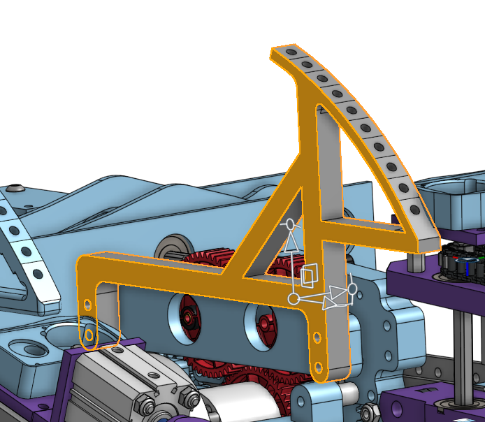
Author: Patrick Shu
Participants:
Update on the Hood: Variable Hood Mount V1 has been tested somewhat thoroughly (only tested half of possible variable parameters). Mount v2 (above) will be printed and tested tomorrow
Here is a list of parameters that can and will be tested for the hood and ramp:
So far hood angle, ramp angle, and vertical compression have been thoroughly tested
Flex, horizontal spacing, and contact angle have all been tested somewhat but not been optimized
Peter tried a new idea which is to use something (in this case dragonflex wheels) as a “pivot” for the flywheel to acclerate the triball around to achieve the most optimal flight path
The shot probability currently sits at around 80%+ on the low end, though it undershoots and only lands 9 ft away, 3ft short of the 12ft target
To improve distance the hood will either need to apply more compression, reducing the flex and compliancy of the whole hood mount/hood, and possibly increasing reducing the hood angle (angled for more distance)
hoodv2 will also have 4 mounting holes instead of 2
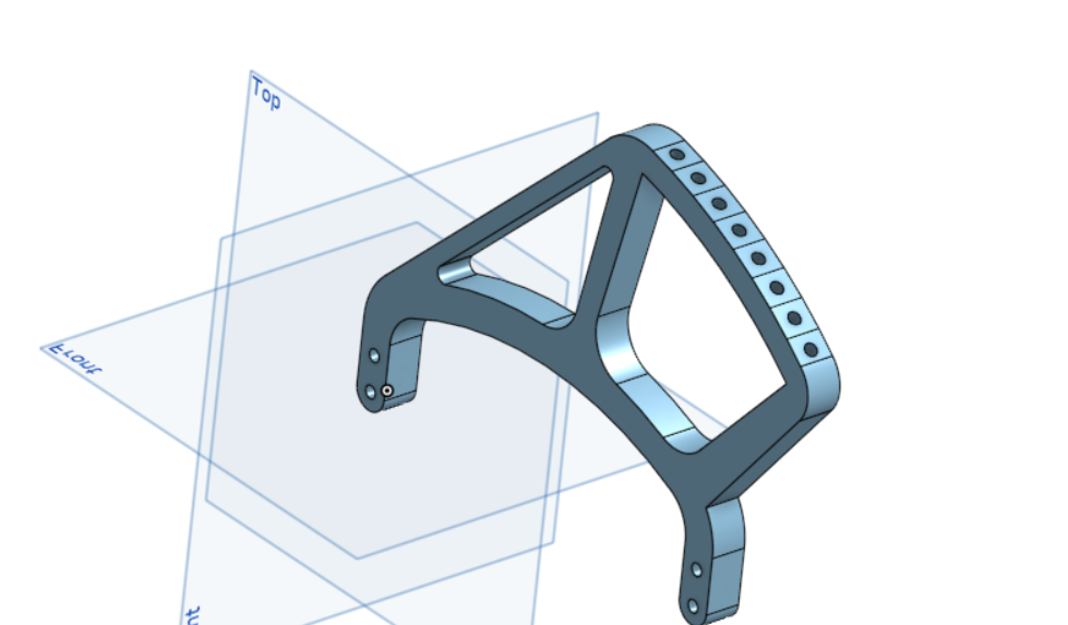
Author: Nikola Nikolov
Participants: Kieran Green, Charles Lapointe, Benjamin Battye, Cal
Parker, Nikola Nikolov, Liam Doris, Rishi Tulsiani
Research projects and topics
Everyone: the catcher needs to be compact and capable of deploying and then retracting a net that will catch the balls; the net needs to be able to rotate and direct the balls in a controlled manner down to the mechanism that will place them under the net.
This week, you will choose a topic to research, and you will start thinking about how we will accomplish this. Feel free to draw a sketch of the full mechanism or write down some notes that are relevant to the topics below.
Choose a topic and research the topic you are most interested in. Write your name beside it and try to distribute it evenly (at least one person per topic).
Possible materials for the net - Ben
Deployable and retractable mechanisms - Liam
Research different mechanisms
Material research - Kierasn
Author: Nikola Nikolov
Participants: Kieran Green, Charles Lapointe, Benjamin Battye, Cal
Parker, Nikola Nikolov, Liam Doris, Rishi Tulsiani
Week 1
Upcoming:
Start of Cad/printing first prototypes
Author: Nikola Nikolov
Participants: Kieran Green, Charles Lapointe, Benjamin Battye, Cal
Parker, Nikola Nikolov, Liam Doris, Rishi Tulsiani
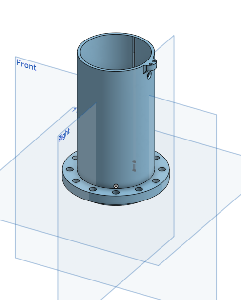
Now going over CAD from the shared folder in OnShape
- Went over importing files to OnShape and how to do it effectively
- Extendable rods will be in the 2 ear-looking holes. on the front (around the edge of the gear) make the hinges for the fingers to attach.
- Make pistons that actuate the fingers
hinges with fingers attached
cal/Kieran - working on the motor mount that rotates the gear from side to side.
went over the finger part of the design, how they should be actuated by 1 piston to open/close, and a rough sketch for visual representation
Established Fridays 5-6:30 PM will from now on be a weekly meeting
Shortly discussed how things should be progressing in the long run and realized that this mechanism will work with lots of different designs/iterations, and lots of prototyping after the prints are done.
Author: Nikola Nikolov
Participants: Kieran Green, Charles Lapointe, Benjamin Battye, Cal
Parker, Nikola Nikolov, Liam Doris, Rishi Tulsiani
Week 4
Cal- rotation base
went over CAD, and gave feedback. when you put the mounts for the telescope on the base, the net will no longer be able to rotate I recommend you put it on the gear part. I also think you should change the mounting design because friction fitting is not a secure way of mounting parts on the robot, as It will most likely be pushed around and hit. Make sure the whole is the right diameter for vex Make sure they are 180 degrees apart from each other Remove the mounting things CAD it in OnShape Next step Make a flange that holds the rotating part of the mechanism down
Different expanding and retraction mechanisms
ben - flick out deploy
3 sections are connected by pivots that can extended
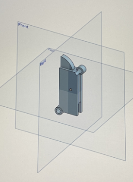 |
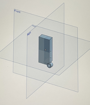 |
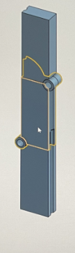
The design was scraped as the mechanism could not retract
Liam - windshield wiper design
2 arms that pivot and function like windshield wipers.
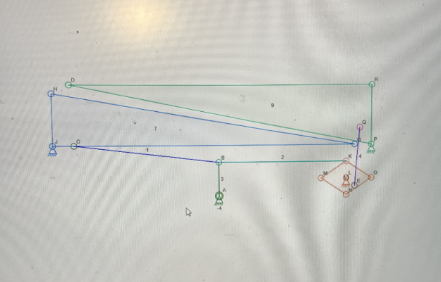
The design was scraped as the mechanism could not rotate and needed substantial space on the robot.
Nikola - light saber design
 |
This design was chosen to be developed
Problems
Rishi -fingers
Improvement points
Next steps
Author: Nikola Nikolov
Participants: Kieran Green, Charles Lapointe, Benjamin Battye, Cal
Parker, Nikola Nikolov, Liam Doris, Rishi Tulsiani
Improve cads and testing
 |
 |
 |
 |
Individual parts were put together as a test which lead to a lot of room for improvement.
 |
 |
Author: Michael Cassidy
Participants: Michael Cassidy, Avery McFadden, Gregory Kelly, Utomobong
Essien, Jacob Antonious, David Colaco
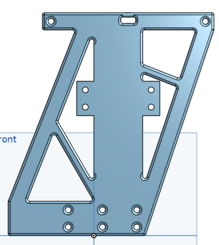
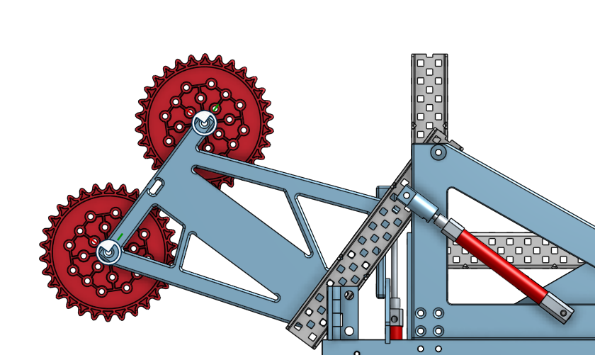
Author: Michael Cassidy
Participants: Michael Cassidy, Avery McFadden, Gregory Kelly, David
Colaco
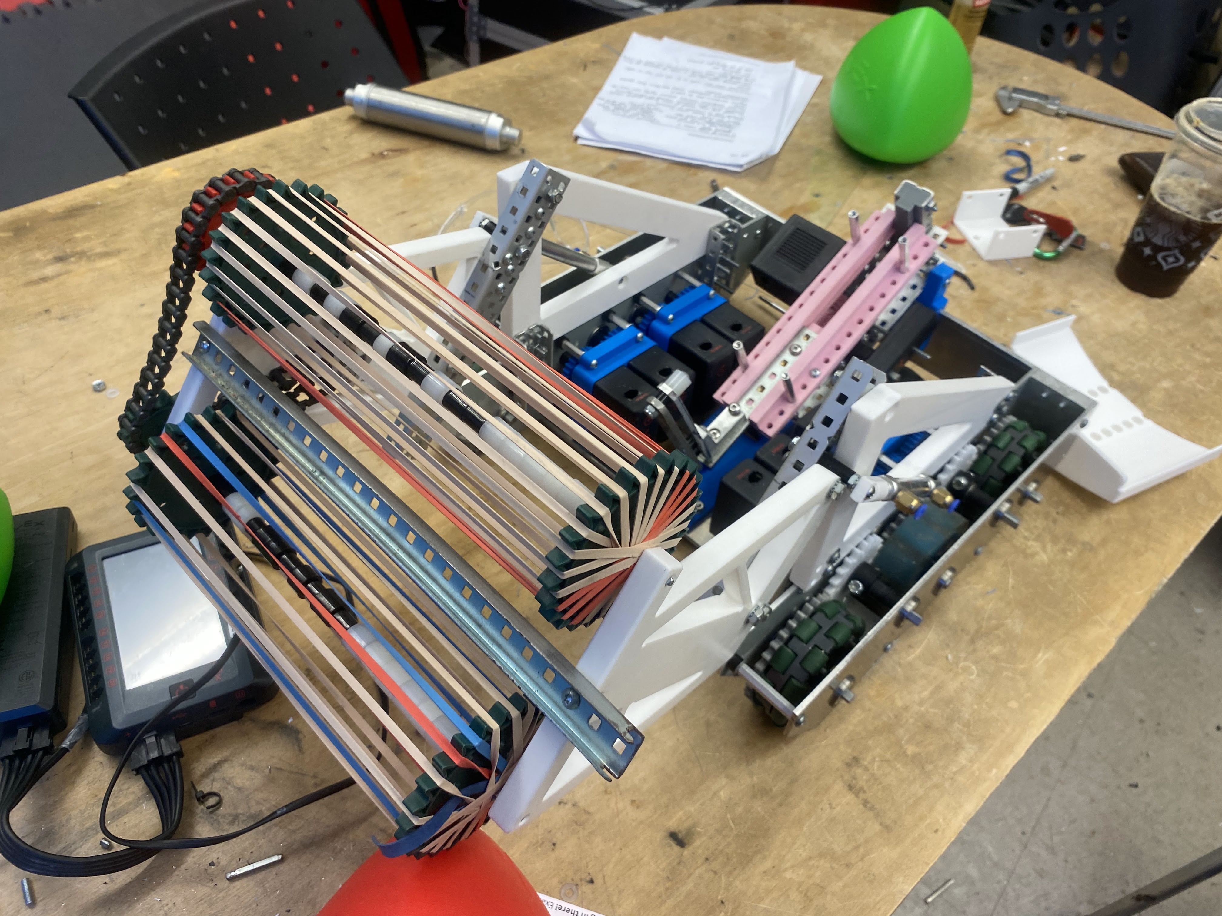 |
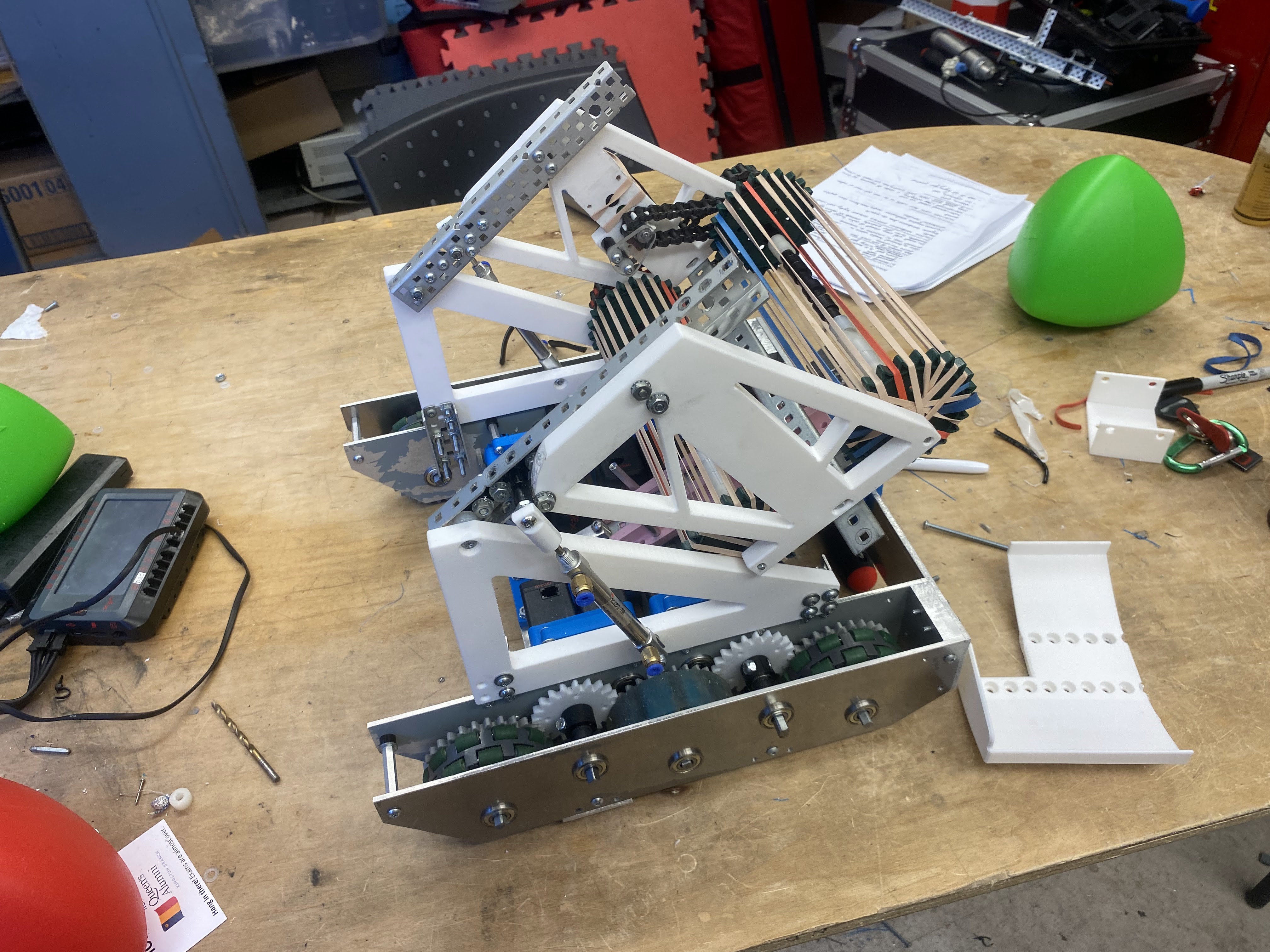 |
Author: Will Steedman
Participants: Xan Giuliani, Peter Tennant, Will Steedman
Author: Will Steedman
Participants:
Introduced project, including parameters, design options and brainstorming
Asked general members to think about the design possibilities and come back to discuss next day
Signed up members for OnShape and gave introductory lesson on how to use the software
Author: Will Steedman
Participants:
Designing CAD models for Intake
Delegating tasks/responsibilities
Deadline for CAD in one week
Author: Will Steedman
Participants:
Final CAD due — met with members to do a design review and discusses areas for improvement.
Improvements were carried out over the next three days and parts were printed for assembly starting March 1
Author: Will Steedman
Participants:
Assemble of intake V1 — included removing supports from printed parts, soldering heated inserts into slot holes, screwing components together, tensioning belt + pulley system and doing preliminary testing with intakes.
Author: Will Steedman
Participants:
Decided on a design with the team, delegated CADding responsibilities and began to CAD mechanism in a shared OnShape Document
Gave team members a week to complete their CAD models
Taught more important design skills to members
Author: Will Steedman
Participants:
RE-Cadded Intake after preliminary testing on March 3 — team members helped convert belt+pulley system into chain+sprocket system. Parts were re-printed and geared for assembly on March 8.
Author: Will Steedman
Participants:
What is the purpose of this meeting? What do you hope to accomplish?
We assembled V2 of the intakes— prepared 3D printed parts, disassembled V1 and put together V2. Featured of V2 includes chain and sprocket system, HS shafts for support and new mounting holes
V2 of intake was very successful and the intakes are working to spec.
Author: Rebecca Reed
Participants: Andromeda Finlayson, Jaiden Relouw, Maya Fijalkowski,
Rebecca Reed
The team started reviewing and creating preliminary designs on paper. This included a 4-bar lifting mechanism, driving up the pole with wheels, or a simple hanging pully mechanism. The drawings included general requirements and placement but no official materials or positioning. The team also estimated the weight of the robot (15kg) to calculate the motors and gear ratio. The team determined two motors with a 4:1 gear ratio.
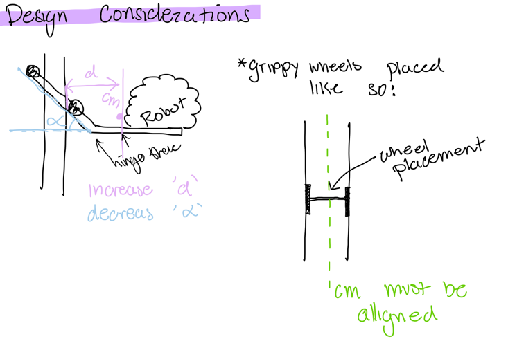 |
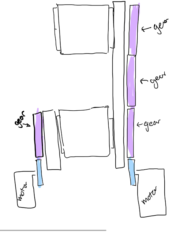 |
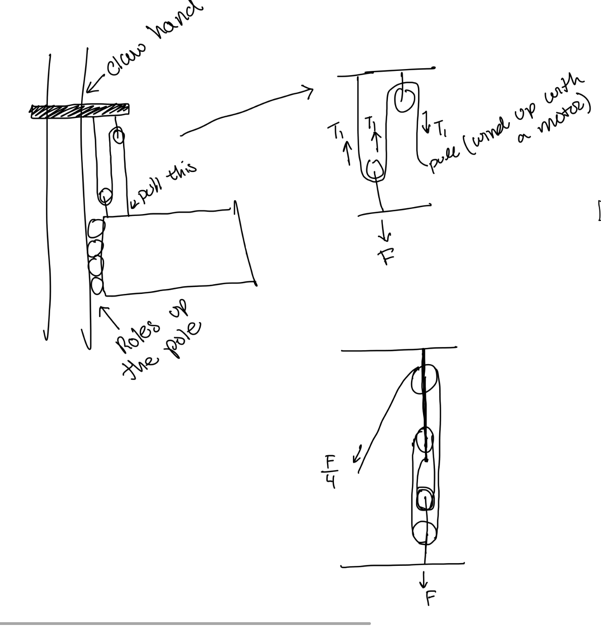 |
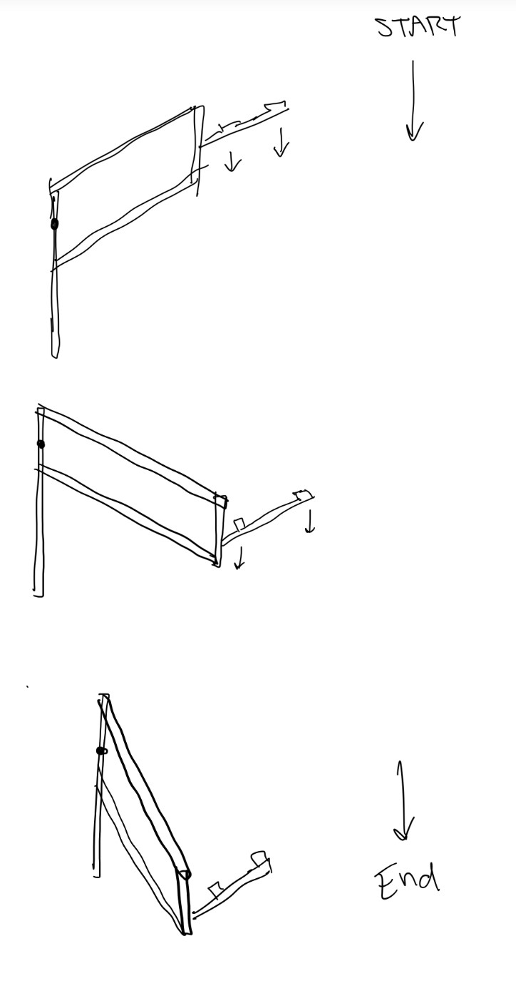 |
Author: Rebecca Reed
Participants: Andromeda Finlayson, Jaiden Relouw, Maya Fijalkowski,
Rebecca Reed
We decided to plan two designs: driving up the pole and four-bar arm. The start of the meeting started with assembly a ‘1D’ four-bar arm and testing different places for the motor and gears. The two main positions were having the motors on a separate piece then the lift mechanism or placing the motor on a vertical piece with the gears fastened to a rotating piece. To create a high enough climb with the given space constraints was quite difficult. Attempts included a mechanism that rotated in two directions, the first rotated from beside the robot to the appropriate climb position, and the second rotated lifting it vertically. This would create a significantly weaker design with an overly complicated structure to build. Another design aspect that began on paper during the meeting was a clamping mechanism that would use friction to stay on the pole. The design began as a square with one side attached to a hinge. Originally it was going to be controlled by pneumatics and a spring. This design was not ideal as it could fail through pneumatic air tank running out by the end of the match or the spring deforming due to the overuse and weight of the robot. This design was then modified to use the force of the pole to shut and latch the mechanism. This removed the possible failures ensuring the mechanism would wrap around the pole every time.
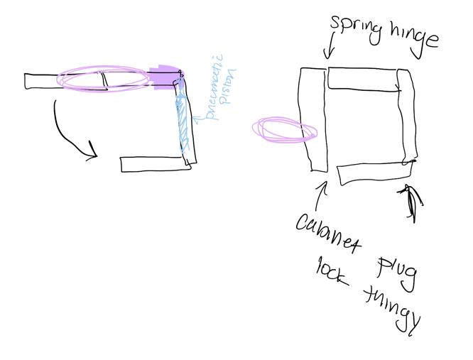 |
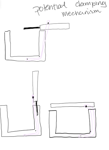 |
Author: Rebecca Reed
Participants: Jaiden Relouw, Maya Fijalkowski, Rebecca Reed
The drawing of the clamp was build using c-channels, elastic bands, a pen spring for the latch, a standoff to set the mechanism ‘off’, and screw hinges. The locking mechanism included the spring for the latched intertwined with a sanded down plastic screw created a angle at the tope allowing movement from one side. This was the ultimately decided upon ‘lock’ for the mechanism as it is simple and small. Other locks that were evaluated included ‘porcupine quill’ type design or a hook. The porcupine quill design would be created with a foldable arrow at the end of a c-channel allowing for the lock to be activated with force. The other two debated locked were evaluated to be either too complicated or not reliable enough. This was tested and shown to work quite well. Although this design was ready to build a more permanent version, because the team was not sure the four-bar lift was going to be built it was set aside for later evaluation
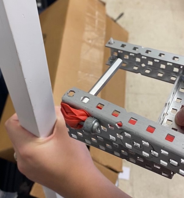 |
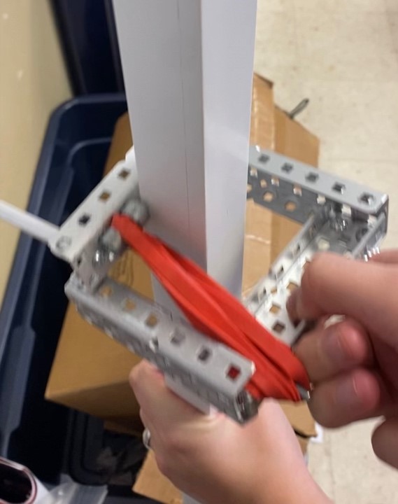 |
Author: Rebecca Reed
Participants: Andromeda Finlayson, Jaiden Relouw, Maya Fijalkowski
During the meeting the team discussed the simplicity of a drive climb design and decided to continue with this and hold off on the four-bar linkage. Two different types of climbs were assembled during this meeting, the first was designed to drive diagonally up the pole while the second used friction and the weight of the robot to climb up the pole with wheels on opposite sides. The first prototype was built to be tested at a later meeting.
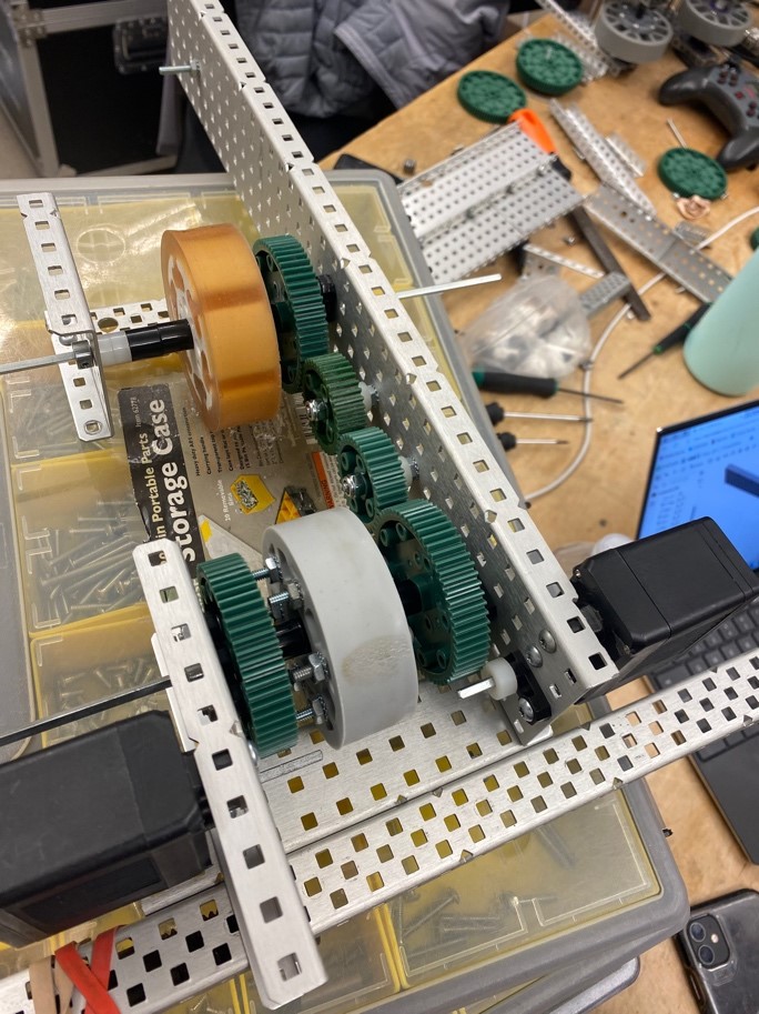
Author: Rebecca Reed
Participants: Andromeda Finlayson, Jaiden Relouw, Maya Fijalkowski
The first test was made, the diagonal design drove off the pole; additionally, the friction combined with the horizontal velocity of the wheels were not enough to keep this on the pole. Future iterations were planned to add extra wheels on the inner surface preventing the mechanism from driving off. The first test of the second mechanism (once the center mass of the climb was balanced with the center of the pole) worked; required modifications included a stronger frame including cross bars preventing twist and smaller wheels allowing less torque back on the motor. The two preliminary designs were also quite bulky. To attempt a fix to this the team discussed using planetary gears, secondary gear trains, using bevel gears, or 3D printing custom gears.
The team began working on a compact CAD design of the two designs.
|
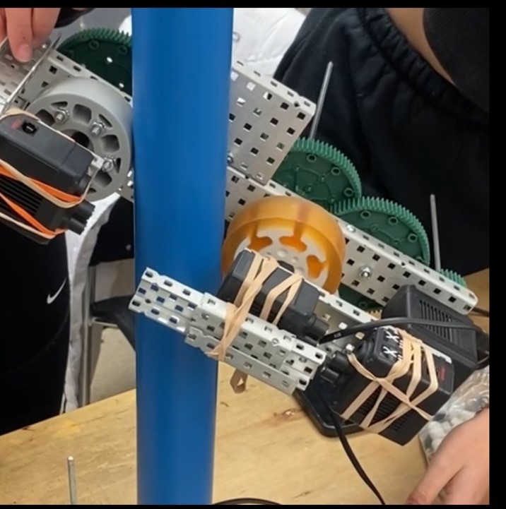 |
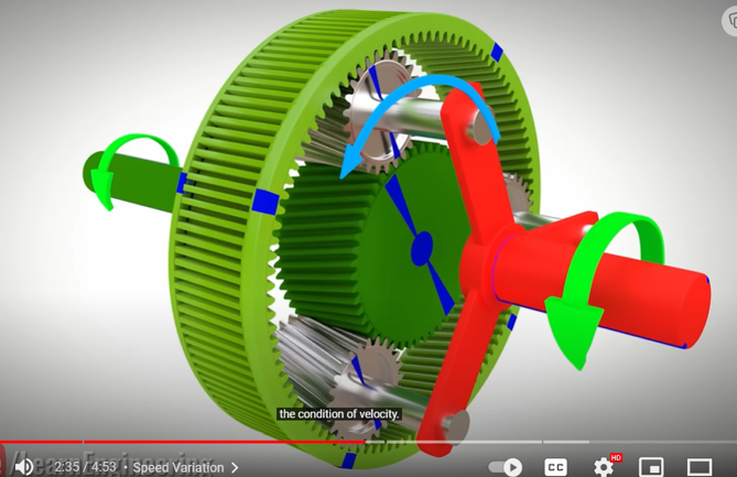 |
Author: Rebecca Reed
Participants: Jaiden Relouw, Maya Fijalkowski, Rebecca Reed
The team then decided to stop iterating the diagonal driving climb as the iterations were more work than beneficial to the team. This allowed more time focusing on a single climb design allowing for more fine tuning. A more robust mechanism was built and tested with a weight to simulate the robot. This design worked, however still needed to be slimmed down.
A Ratchet and Pawl was designed in SolidWorks to be printed as the mechanical stop preventing the mechanism from rolling downwards.
The team decided on hinges and pneumatics to allow the climb mechanism to be connected inside the robot during the game and pushed out at an angle during endgame.
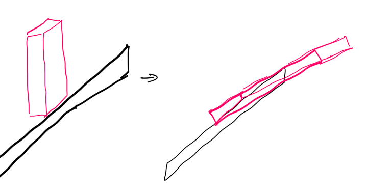 |
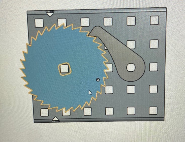 |
Author: Rebecca Reed
Participants: Jaiden Relouw, Maya Fijalkowski
The first CAD model was completed, and version one of the climbs was built using a polycarbonate ‘C’ to prevent twisting, two wheels with a 2” diameter. And the ratchet stops any reverse movement. To test the design without jeopardizing the robot itself, weight was added to the appropriate location to simulate the robot. The design successfully climbed the pole, however the ratchet yielded.
The design was built with many spare parts and will be rebuilt with proper materials.
Hinges were tested for strength.
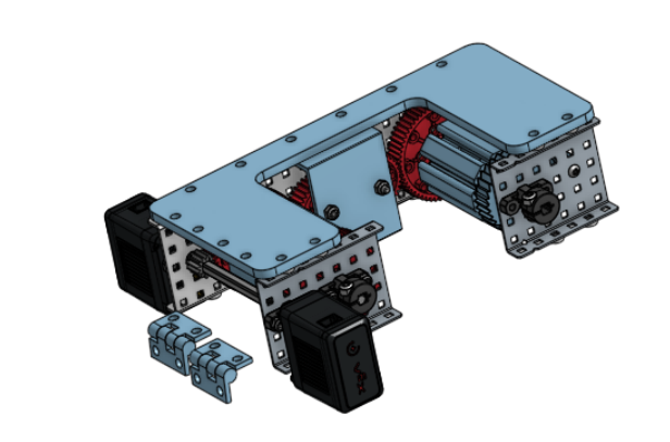
Author: Rebecca Reed
Participants: Jaiden Relouw, Maya Fijalkowski, Rebecca Reed
Once the ordered hinges arrived, they were placed on a c-channel with a screw going all the way through allowing for the weight of the robot’s weight to be distributed more evenly through the Aluminum to prevent deformation. Additionally, the climb was re-assembled with custom cut c-channels, newly 3D printed ratchets, 3D printed supports, newly molded wheels, and polycarbonate ‘C’ shapes for support.
The ratchet was tested for failure, it did not pass the test. The future ratchet will be designed to allow aluminum inserts and have a lower number of teeth which increases the force allowance.
The current built design did not match the width requirements.
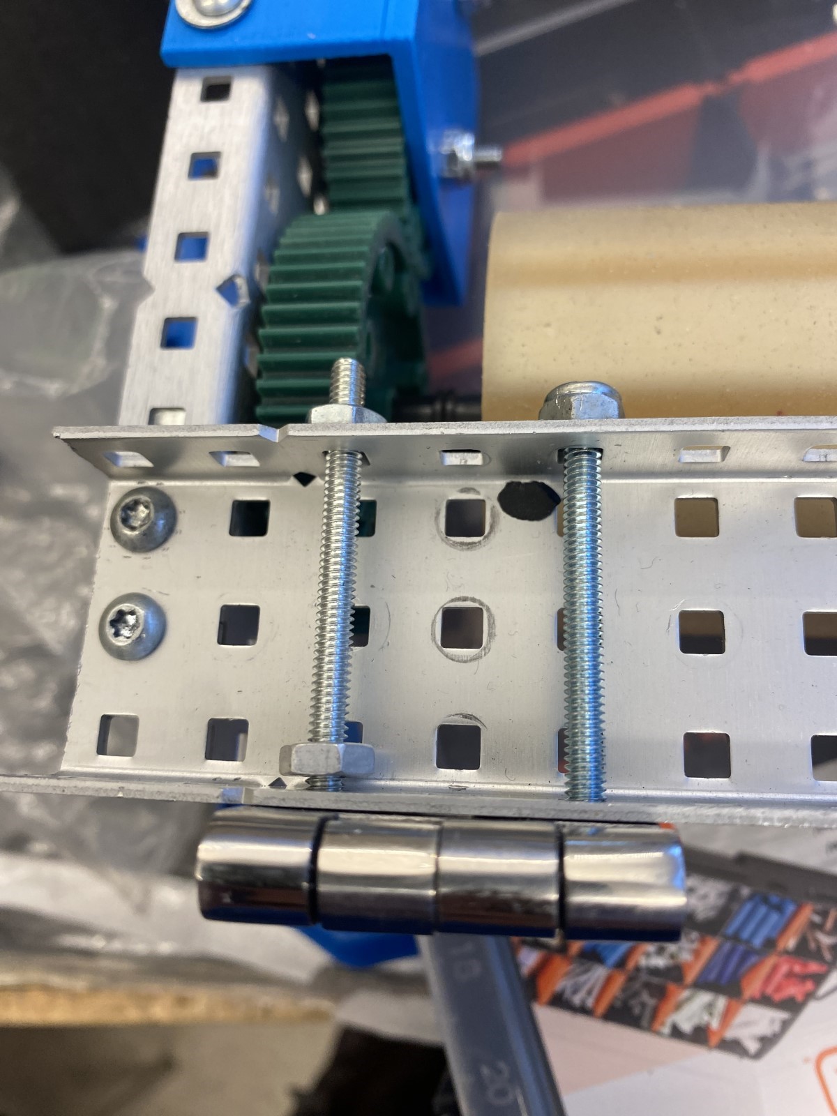 |
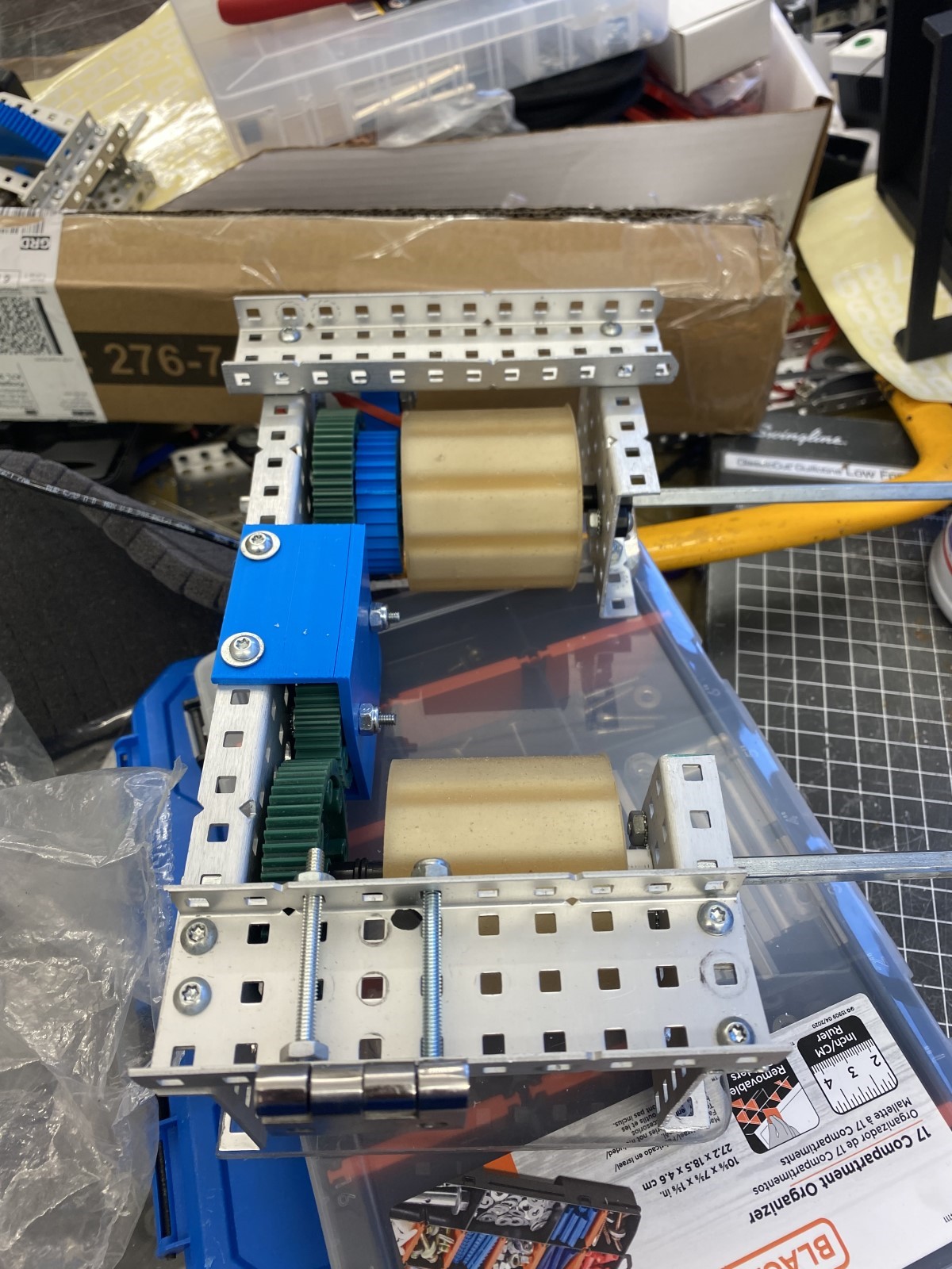 |
Author: Rebecca Reed
Participants: Michael Cassidy, Jaiden Relouw, Maya Fijalkowski, Rebecca
Reed
To thin the design, 3D printed sides were designed in SolidWorks and an aluminum piece replaced the polycarbonate. An extra 12 Tooth gear was added to the gear train to prevent the wheel and motor from overlapping while keeping them on the same side to save space. Unfortunately, this design did not account for the wire to connect the motor to the brain. Two approaches taken was to squish the wire as much as possible and hope that it does not drag on the wheel creating extra friction, adding an extra gear in the gear train extending everything by an inch, or to flip the motor around adding extra gears into the gear train. Extending the design by an inch would not work as it was too long for the robot, squishing the wire was not ideal as it ruins the wire and has a small tolerance and high chance for error, and flipping the motor created overlaps between screws and the motor. The overlapped motor and screws could be fixed by indenting more whole causing for a weaker print. One attachment point between the 3D print and the newly created aluminum ‘C’ was also compromised.
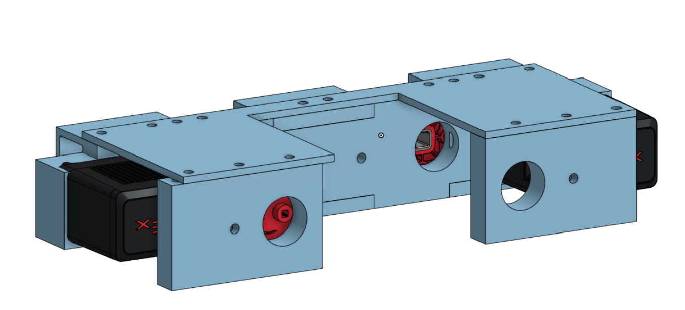
Author: Rebecca Reed
Participants: Michael Cassidy, Rebecca Reed
The new climb was assembled using the custom 3D printed parts, not including a ratchet. The two-aluminum cut ‘C’ pieces assembled on the outsides of the 3D printed design. The original ratchet made to fit the slim specifications, so was not added to the assembly. This design was tested without the robot on the pole to ensure the smaller gear ratio and smaller wheels were functional. The battery wire and wheels were very close in proximity and therefore the wires were zip tied back to allow tolerance.
Author: Rebecca Reed
Participants: Jaiden Relouw, Maya Fijalkowski, Rebecca Reed
The ratchet was re-modeled to have larger teeth (enable more force on each tooth). Two types of ratchets were modeled. One with 9 teeth, and one with 18 teeth. This is to test which is more desirable, slightly stronger force allowance or a wider range of angles the system will be able to stop. Each gear was designed to allow for an aluminum insert; this modification may not be functional due to the small edges it creates near the ratchet gear teeth.
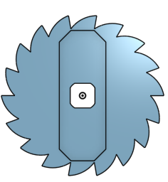 |
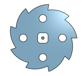 |
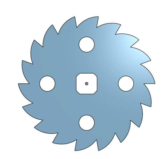 |
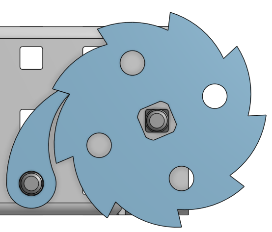 |
Author: Rebecca Reed
Participants: Michael Cassidy, Rebecca Reed
The final Prototype of climb was assembled and tested attached to the robot. This test was successful. The last step is the design the output mechanism to put the climb mechanism on.
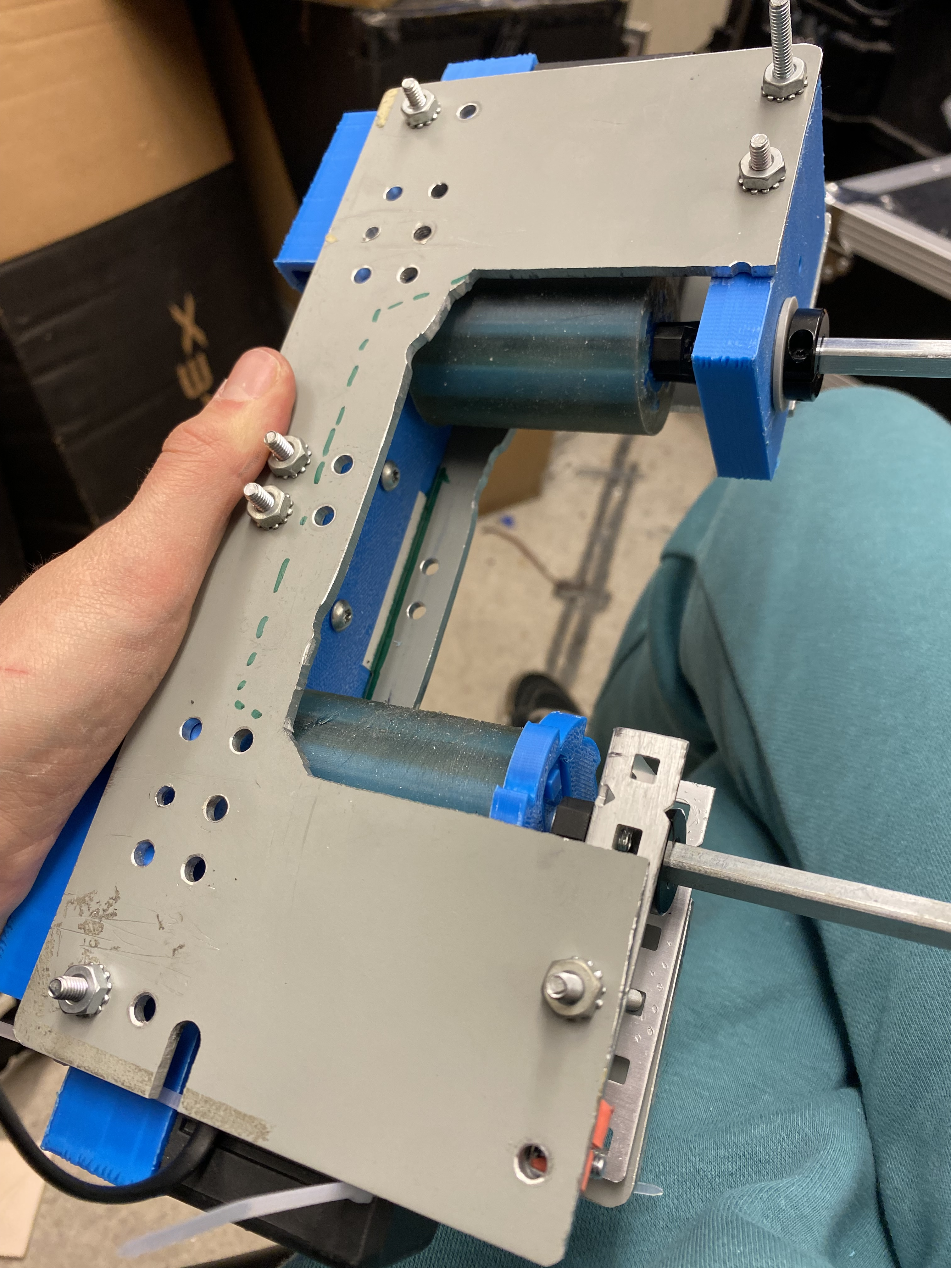
Author: Rebecca Reed
Participants: Xan Giuliani, Rebecca Reed
We worked on preliminary designs for the world’s climb. A few ideas included an elevator, a four bar, or pulleys. The team decided on a four bar type climb and continued to calculate the torque required. This was done using Newtons balance equations. The team calculated that 3 motors would be sufficient. Additionally, there would be two bars. On one side it would connect to the robot with a free turning join, and on the other side it would connect to a claw type hand with a free turning joint. The powered rotation will be in between the two bars.
Author: Rebecca Reed
Participants: Andromeda Finlayson, Xan Giuliani, Jaiden Relouw, Maya
Fijalkowski
During this meeting the CAD of climb began. Similar to the originally designed claw, jaiden and maya began planning out a stronger version. The side pannels were designed to have cut outs for a lighter build spaced to allow the too arm to go inside the bottom arm. Torsion springs will be placed at each joint to add tension allowing the mechanism to go to the correct location to mount the pole when released. A physical stop placed at the robots base with a 15 degree angle with respect to the vertical will be added to ensure that there will not be any sag and the base of the second robot will be at the highest climb. The connection between robots has not been decided. This work was split up within the group.
Author: Rebecca Reed
Participants: Jaiden Relouw, Maya Fijalkowski, Rebecca Reed
The clim claw design continued in onShape creating a 3.8” claw. Technical details in the climb were also determined. This included what length each arm will be, where the motors will be placed on the drive train, where each physical stop will be, and what will lock the mechanism at the top. The arm lengths will be 15” and 20” for the bottom and top arm respectively. The motors will be placed in a stack with 0.1” spacers in between allowing 36 tooth gears to be connected between each motor and the climb. This stack will be placed on the left of the intake. There will be a physical stop preventing the claw from going past 180* from the top arm and a physical stop preventing the bottom arm from going past 15* from the vertical. The drive train physical stop will be on the inside of the drive train wall. When the climb is complete and the power is turned off, the climb will be locked in place with tension spring loaded stops. Next meeting, the CAD will be completed and the spring constants will be calculated.
Author: Rebecca Reed
Participants:
The team calculated the spring constants required to ‘spring’ the arm design upwards into the right position to clamp onto the pole. This design used one belt rotating at the first joint. The cad begun by design the two wall that were rectangles with triangular cut outs to reduce material and weight. Physical stops were added the back of the bar to ensure that even though the arm was in tension, the angle would not become to large and un ideal to clamping onto the pole.
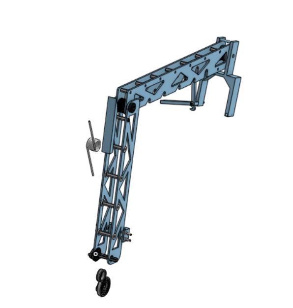
In the next meeting, the team plans on manufacturing the components.
Author: Rebecca Reed
Participants:
During this meeting, the team took 1/8 inch pieces of aluminum and sketched everything out to be cut on a belt saw. The team cut four bars, attached it with standoffs and added a belt to allow the stack of motors to control the center joint while remaining on the drive train.
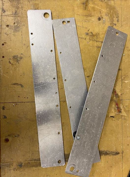
the next meeting to be held at the beginning of next week will be assembly and testing.
Author: Rebecca Reed
Participants:
The new climb was assembled and one motor was attached to the base to test if the motion was correct. Unfortunately not. The rotation was at the center joint and the thought process was that the arm would be able to lever itself up, but the free joint at the claw was not fully thought through. Because of this another belt was going to be added to add rotation at the claw. This plan was not possible due to the product being out of stock.
The team is going to design a new climb arm.
Author: Rebecca Reed
Participants:
Because the test of the arm was not successful, the design was re thought out. The design could not be any larger due to space requirements on the robot, so an arm of some sort had to be created.
Because of this a second version of the arm was created. As shown the second version of the arm had much more mechanical advantage allowing the lever arm to pull the robot up. This design still lacked control over the claw though. The original idea was to create a pneumatically controlled claw, this would not work though as two robots would not be moved by one piston. This also added the risk of running out of air at the end of the game and not being able to climb.
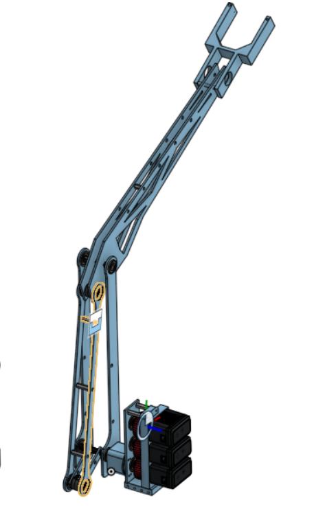 |
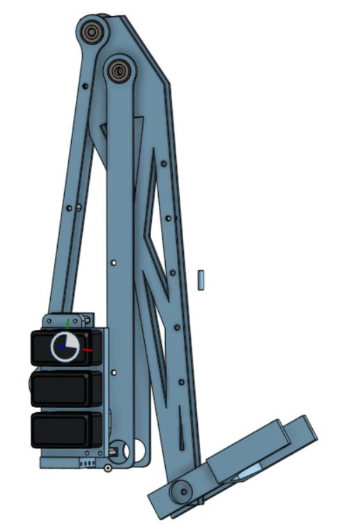 |
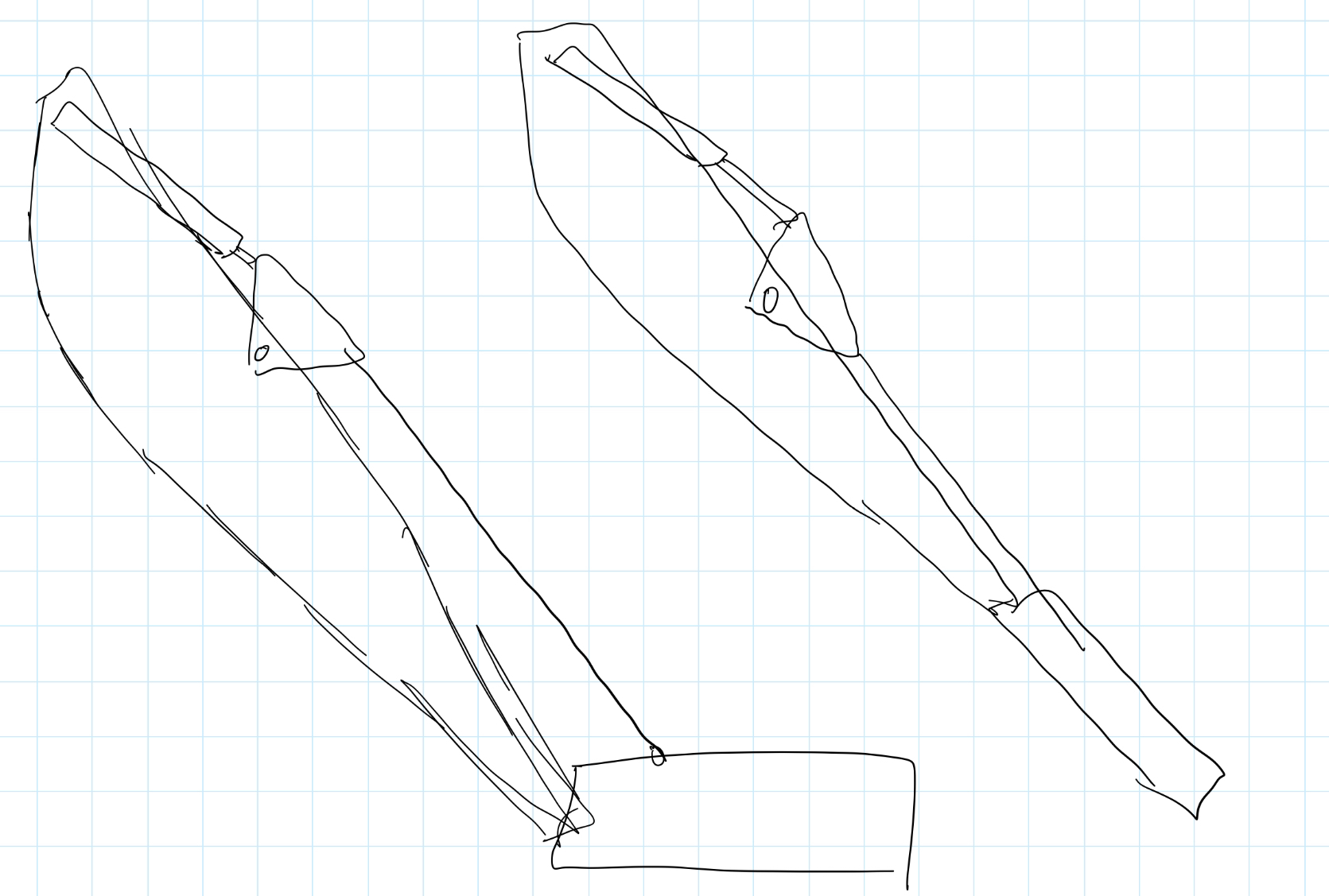 |
Figure out a better controlled arm.
Author: Rebecca Reed
Participants:
For this new design to work while not using two belts, the design was ‘reversed’. Instead of using a four bar to control the top arm, the four bar was added to control the claw-arm angle. Again, a belt was added to have this motion while the motors remained on the bot.
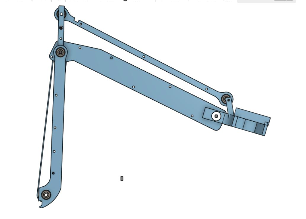
The plan for deployment was still keeping the arm in tension to the desired height for mounting to the pole and then releasing it during the end game.
Physical stops at 15 and 34 degrees would be added at the base and the first joint respectively.
During this time, the claw design was being CADed using a new piece of a aluminum. The idea was to keep one side in tension allowing the tension to be released an transition to the other side of the claw when hit by the pole. A physical stop was added at the joint between the claw and the pole to ensure the claw could never go to far.
A hook was also added to ensure the arm could not get undone once the claw had hooked.
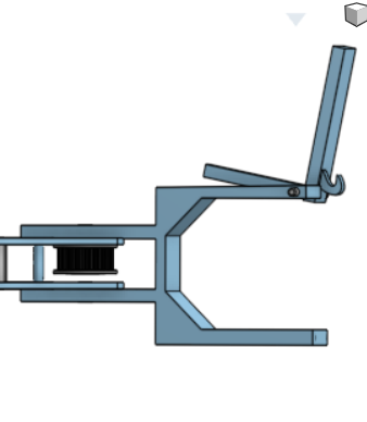
cut out the new cad design in 1/8 inch aluminum sheets
Author: Rebecca Reed
Participants:
This meeting the arm was assembled. However, due to the belt not fitting properly, the arm could not be tested.
There were also second thoughts about how the mechanism worked. The current design controlled the angle of the claw, and doing so would lift the arm upwards, climbing to the top of the pole.
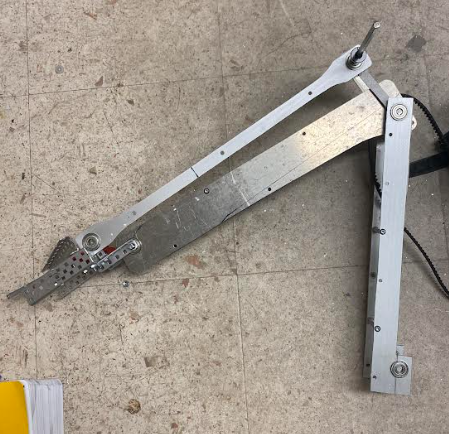
The new suggestion was to build a regular four bar. This caused many space issues. In attempt to fix these issues, the bar was changed to may shapes and the design was widened. None could match the current space issues.
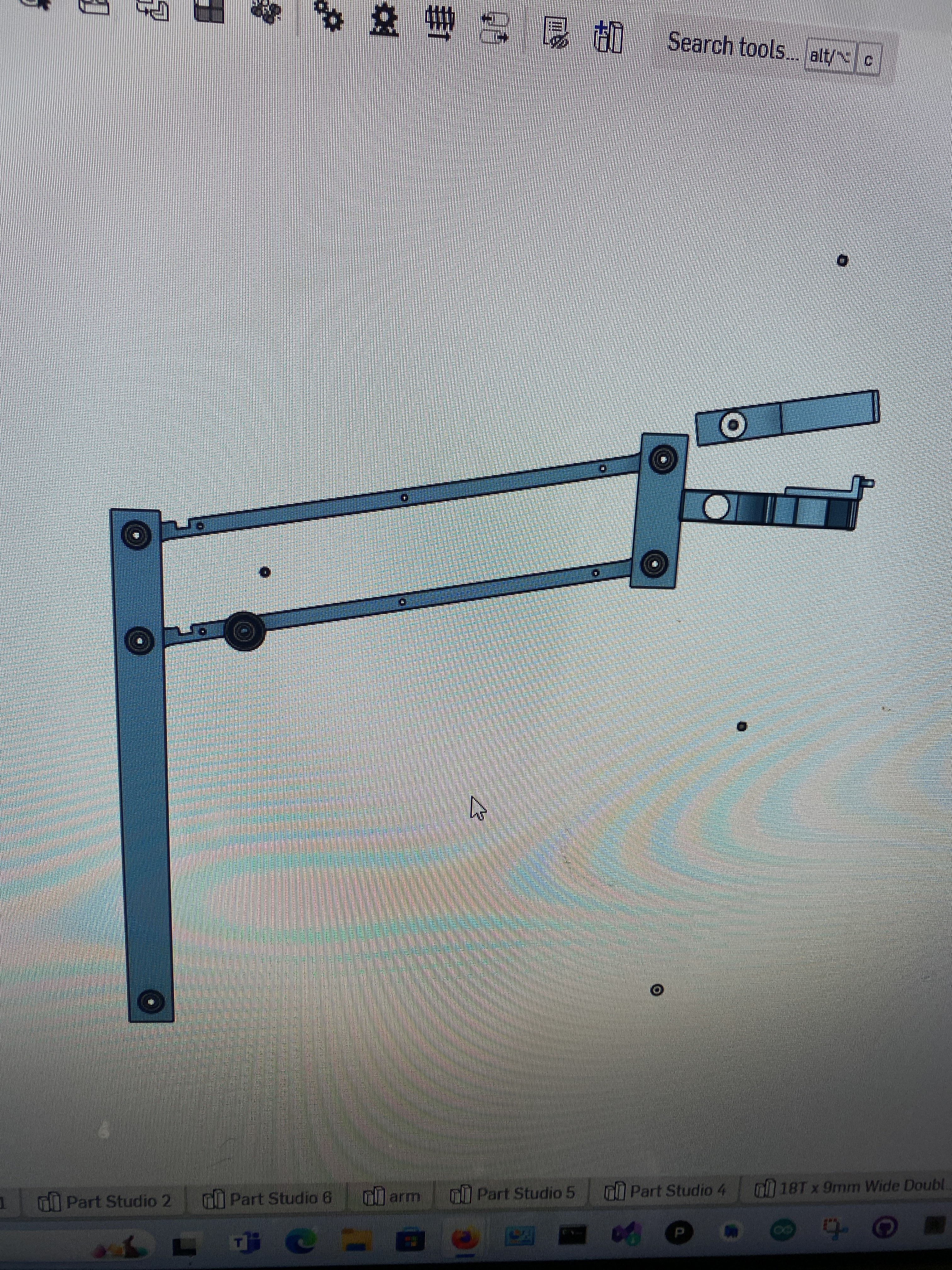
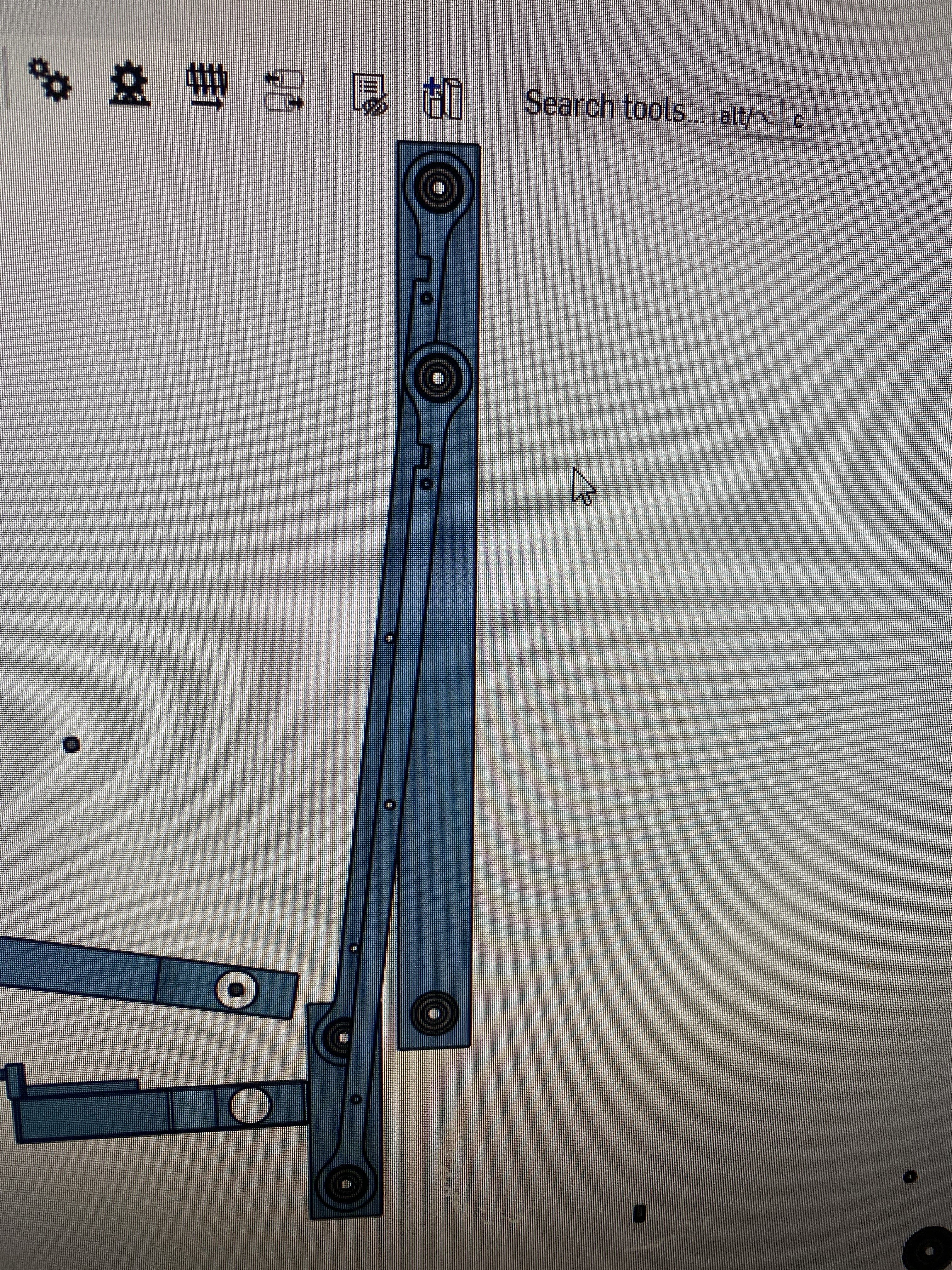
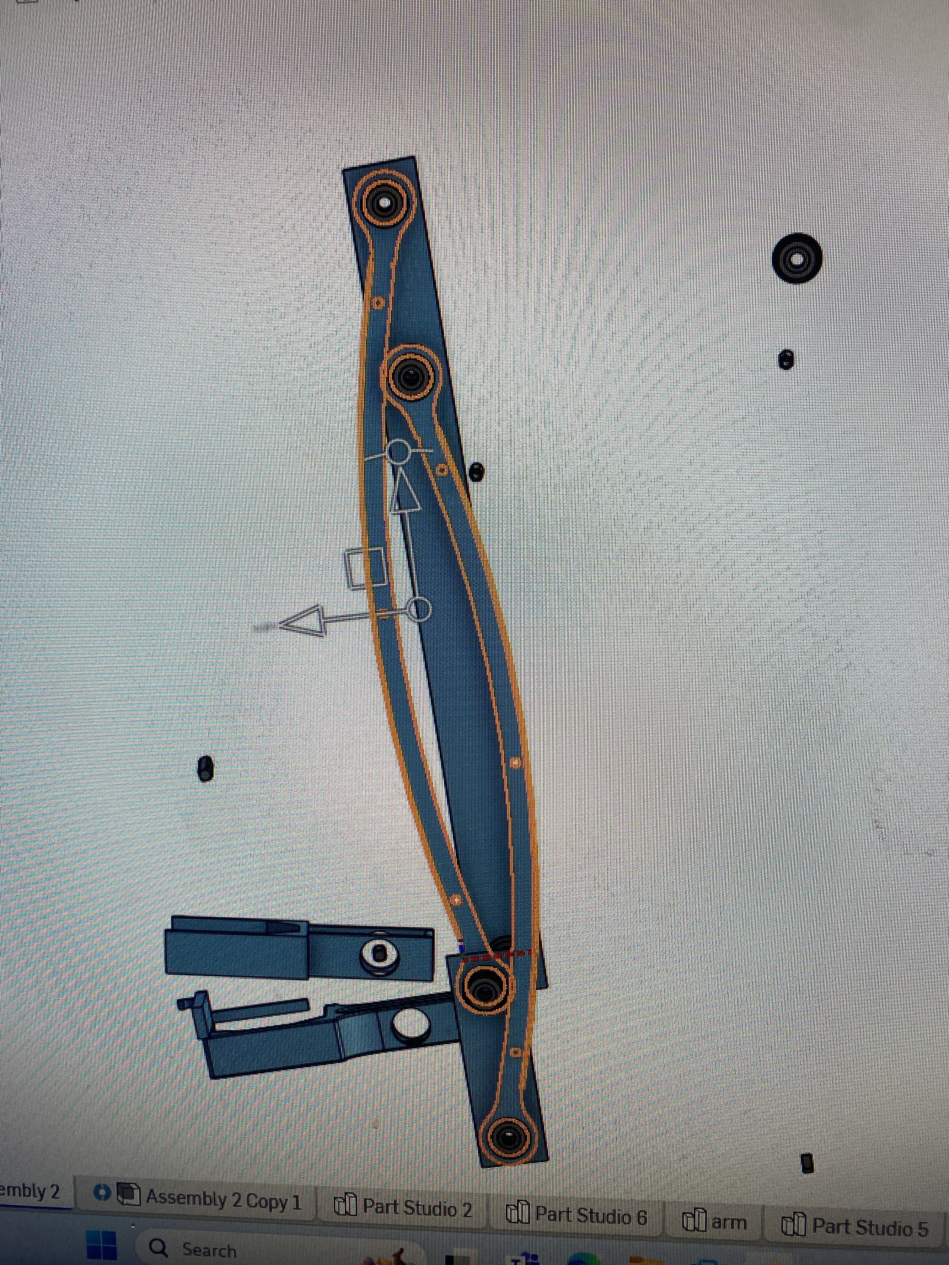
Author: Rebecca Reed
Participants:
Now that the CAD design of the arm had been made to the correct size, manufacturing could begin. This was done again with a belt saw. The holes were measured, center punched, and drilled. The four bar top pieces were created and inserted with the bearings.
Hopefully, in future center holes will be cut to lighten the load.
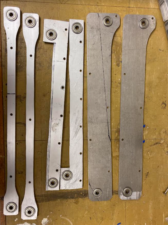
assembly and testing
Author: Rebecca Reed
Participants:
The new Climb idea got in the way of the shooting mechanism so a new version had to be thought up. The first idea was to change the shape of the top bar to be a banana shape.
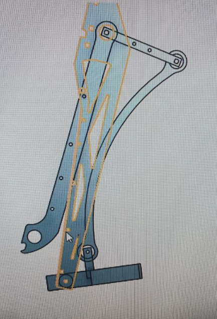
This still worked functionally but was still in the way as the arm was off-centered and the top bar would still be in the way. The robot could not shoot at the desired 22 degrees.
The next idea was to look at belts again, but unfortunately nothing could be purchased. The final idea that did shrink the climb to enable a 22 degree shooting angle was shortening the lever piece and lengthening the ‘bone’ piece.
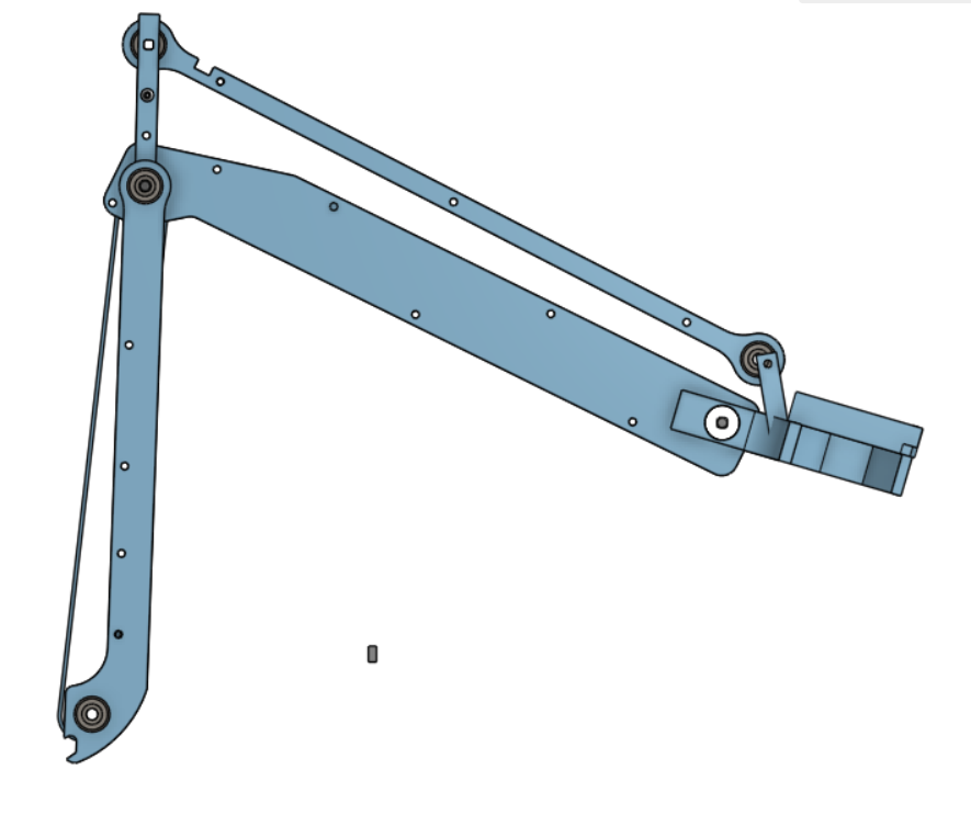
The team also required the robot to be driven in the pole sideways with respect to the arm, so the claw was also redesigned with fillets to increase the strength.
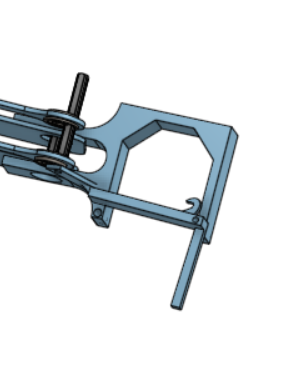
Author: Xan Giuliani
Participants:
We cut out the new arms and began drilling the holes for the bearings. We also continued cadding the claw part and locking mechanism for the arm.
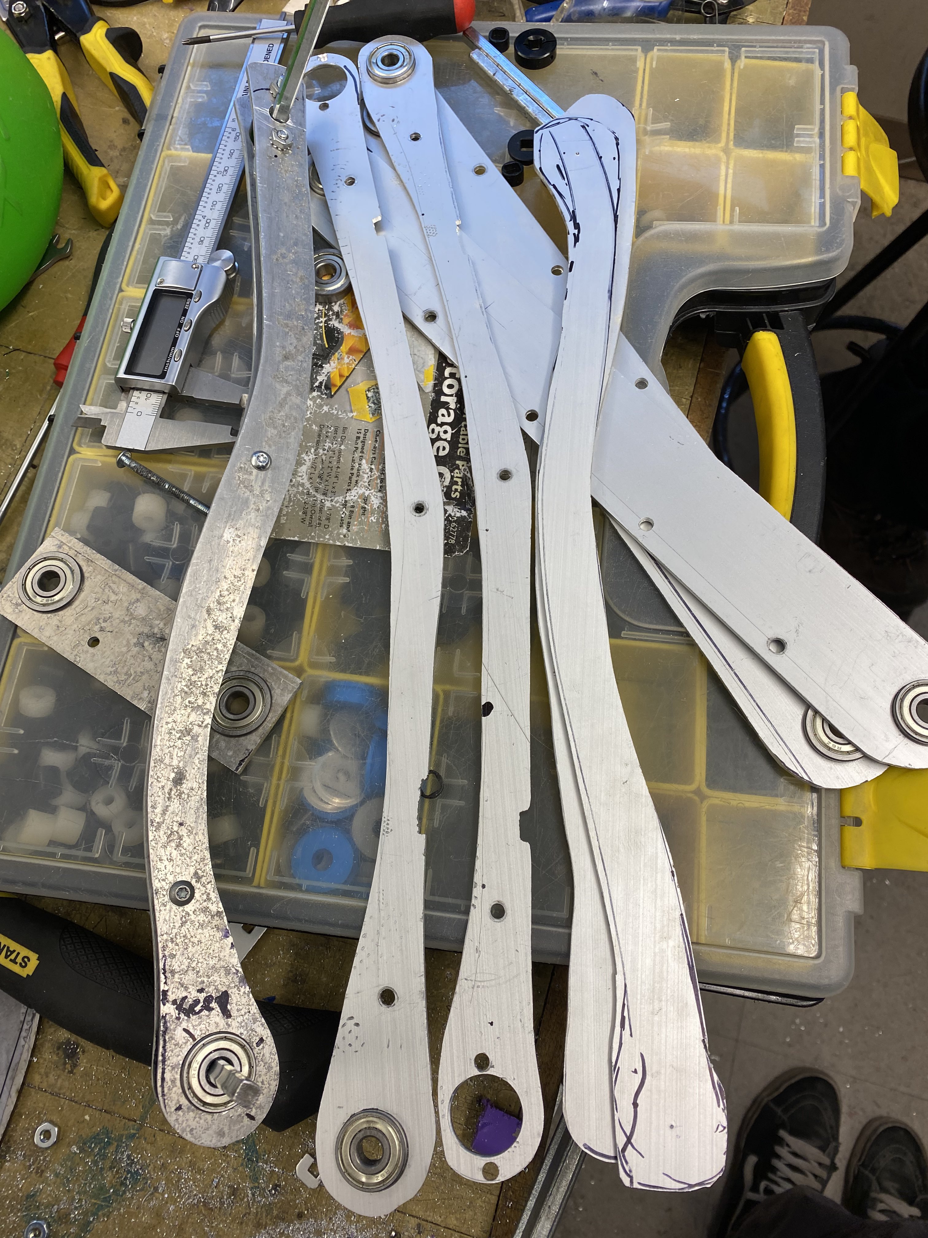
Author: Xan Giuliani
Participants:
Today we finished assembling the arm (without the claw or mounting), and tested the mechanics of it. While the mechanism will work, the bar is too tall and will make the robot too wide to fit between the bar and the wall on each side. We planned a redesign to make the bars slightly shorter to fix this issue.
Author: Mike Stefan
Participants: Michael Cassidy, Kieran Green, Mike Stefan
VEX has introduced a new feature which allows the robots to communicate with each other. We need to create the API which allows us to make use of this feature in vex-rt.
vex-rt uses PROS which is an open-source environment to program the
V5 in C/C++. To turn this into Rust code we use their C API and a Rust
library named bindgen. You can find an example where this was done in
the past with the optical sensor in this commit,
note that this is missing the implementation of From
To complete this project we will need the rust bindings to the PROS VEXLINK API. This should implement a simple packet system which allows non-trivial data structures to be sent between robots. It should also implement a queue which allows multiple threads to act as the sender so that any block of code can safely send data without concern about timing or overloading the buffer.
The code works and you provide well-commented examples of all features. You should also produce an RTIC book style tutorial article for all features.
Author: Mike Stefan
Participants: Michael Cassidy, Kieran Green, Mike Stefan
An easy way to install vex-rt and all of its dependencies for all platforms.
Installing vex-rt, especially on Windows, is a very labour-intensive task which takes longer than necessary. The main cause of this is the number of dependencies the system needs. The goal of this project is to improve this system. You will need to install all of the parts and dependencies of vex-rt as shown in our download instructions document.
This can either be done as an installation wizard, which will have to be created to support all platforms (Windows, Mac, Linux) or it can build off of the PROS VS-Code extension and have it installed like that.
The exact implementation of this is left to the discretion of the assigned developer
This system installs vex-rt on all systems in an easier manner than the current system. It will also have to be easily maintainable and well-documented so that it can be updated by anybody in the future.
Author: Mike Stefan
Participants: Michael Cassidy, Kieran Green, Mike Stefan, Rex Galloway
Fenwick
Create a new version of our Qunit library that better meets our requirements. The current library is overly complicated with several features that are not needed for the system and they hurt its usability. This project will be simplifying the system, including removing support for multi-unit matrices and vectors, setting it up so the compiler can interpolate most variable instances and making it easier for functions to have generic qunit values.
At the start of last year, we used a Rust units library named UOM. This was alright but it has a few large flaws. These flaws included it being so unnecessarily verbose that it was annoying to program with, and the library made a strong distinction between certain units and some of the operations you can perform. For example, it made it impossible to add two temperatures together. To solve this problem we created Qunit. Unfortunately with qunit, we attempted to include more features than necessary and this project is aiming to correct the issues.
See the existing library and its API. Make the removals and improvements described in the outline while keeping a similar interface. All data types created in this library should implement serde serialize and deserialize.
All changes work as intended. As you are working, create a test example for each new feature added, and features changed. These examples should be well-commented and would be able to be posted as resources. Every method should be properly documented so that the docs.rs page is accurate. With this, you will also need to complete a RTIC style documentation book chapter.
Author: Mike Stefan
Participants: Michael Cassidy, Kieran Green, Mike Stefan, Kashan
Rauf
Create a complete and concise documentation and tutorial book in the style of the Rust Book.
Use the existing vex-rt API documentation and examples to create a singular resource that would allow a programmer new to vex-rt to quickly onboard. Another good example of the target product is the RTIC Book. To help with the creation of this site, you can also reference the Rust Books Github.
The website is up to date with all current features in vex-rt and there is a defined way to easily add new examples as we add more features to vex-rt. The website should be easy to maintain and well-documented so that future team members can continue using it.
Author: Mike Stefan
Participants: Nicholas Lefterys, Michael Cassidy, Nick Mertin, Kieran
Green, Mike Stefan
Add the ability to send high-priority comms messages. Right now our system is designed to transmit a lot of data, where it doesn’t matter if one or two packets get lost. This is problematic if we have an important configuration packet that we have to ensure gets sent. This project adds the ability to send a special packet which does this without impeding the rest of the functions of our comms system.
You can find our previous comms code here which worked by sending the packets configured here. You should copy that part of the comms code over to this year’s repository and make the desired changes.
The actual design of this should be discussed with either Nick Mertin or Theo Lemay, which is who designed the existing system. If this section still says this my bad, I intended to do that and I guess ran out of time.
The system works and is stress-tested. You should be able to provide a write-up detailing the limits of the system for our notebook and for future reference when deciding how much information we can share over the bus. You should also create a pair of simple examples, one of normal use and one of a high-priority packet. These examples should be well documented and easy to follow for anybody trying to use your features and should aid in your testing of the system.
Author: Mike Stefan
Participants: Lucas da Silva, Michael Cassidy, Nick Mertin, Kieran
Green, Mike Stefan
Create a timer module which creates generic timers, Instants and Durations regardless of the chip choice, and where that information that is needed from the chip can be passed at initialization.
We will frequently have to use the chip’s hardware timers and having a common infrastructure to do this will help make writing the firmware later. You can find some examples of similar systems in our firmware from last year (here and here), but these examples are not fully generic and have slight differences on both boards. This project is part of an attempt to make as many things as possible the same between both boards to reduce overhead and confusion.
This module will need a timer trait with the common timer functions listen, unlisten, is_clear and clear which can be implemented for each board. It will also need to support TimerDelayFutures (see last year’s timer code), TimerDelays and Instants. In all reasonable places, you should make them implement the math operators (addition, subtraction…) and other common rust traits including clone, copy, debug, serialize and deserialize.
The timers perform as intended and it’s easy to create new ones for a given chipset. You should provide a couple of well-documented examples for all common tasks you might use the timers for.
Author: Laura Cochrane
Participants: Laura Cochrane
Program, in Rust, motion algorithms to control the drivebase of the robot.
Author: Kieran Green
Participants: Kieran Green, Ryan Jacobson, Cole Jowett, Mira Teoli, Ben
Probst, Justin Abuyuan
Went into depth about what all the subteams will be doing and the requirements. Also distributed roles of who is on what sub-team.
Author: Laura Cochrane
Participants: Laura Cochrane
Track robot’s position by using the input of multiple sensors.
Author: John Williamson
Participants: Mike Stefan, Kashan Rauf, Cooper Moses, John Williamson,
Rex Galloway Fenwick, Zachary Kizell
We Realized our internal install process was overly complicated and time-consuming through non-bundled packages. Began the engineering process, identifying core issues, requirements and possible solutions.
Installing the dependencies for the Vex-RT toolset was very time-consuming and not well-streamlined. The current process requires a meeting to show users multiple links to download: the latest Python version, Rust Toolchain, Visual Studio Code, the GNU Arm Embedded Toolchain, LLVM 64, and finally a command prompt to install cargo and pros-cli. All-in-all requires a 17-page installation guide (Found Here).
Potentially Mac compatible if possible, easy for users to run/less required user interaction. Easy Maintenance. Programs must be in the Windows PATH
Began the creation of the advanced installer program adding the prerequisites for each application and bundling them together with 1st version already finished
Author: Laura Cochrane
Participants: Laura Cochrane, Henry Xiu, Phie Tong, Matthew
Stevenson
- Mostly everyone downloaded the necessary software
- Went over some motion algorithm basics
- Looked at the plans for the year and how the subteam will be
organized, as well as a basic timeline of when we want to get things
done by
- Decided on Sunday 7-9 as the weekly meeting time
- Team members will be added to QVEX github within the next couple of
days
Author: Kieran Green
Participants: Vince Song, Kieran Green, Ryan Jacobson, Cole Jowett, Ben
Probst, Davidson Strong
Helped set everyone up on Gitlab and Git Kraken. Went through the old code and explained what we accomplished last year. Talks about how all the parts of the sub-team are going to fit together into one group.
Author: John Williamson
Participants: Mike Stefan, Kashan Rauf, Cooper Moses, John Williamson,
Rex Galloway Fenwick, Zachary Kizell
The Installer needs the QVEX Team’s branding rather than the default advanced installer logo and design.
The default advertised advance installer with their logo over it. We needed one with our team colours and logo, but we didn’t have a bitmap and our current logo had jagged edges and transparency issues
All will have a custom bitmap and banner with options:
Author: John Williamson
Participants: Mike Stefan, Kashan Rauf, Cooper Moses, John Williamson,
Rex Galloway Fenwick, Zachary Kizell
We realized that silent installs might be more user-friendly with less interaction.
we wanted a more unique program that would bundle necessary programs and also silently install such; rather than bundling each package and the user clicking through each of them
Silent install Flags:
Rust: rustup-init -y
/VERYSILENT /NORESTART /MERGETASKS=!runcode
ARM Toolchain: /s
LLVM: Not Possible
Author: Laura Cochrane
Participants: Nick Mertin, Laura Cochrane, Matthew Stevenson, Mira
Teoli, Noel Steves, Sivan Xu
Author: Kieran Green
Participants: Vincent Ho, Kieran Green, Ryan Jacobson, Cole Jowett, Mira
Teoli, Ben Probst, Davidson Strong
Went over deadlines and broke up work that needed to be done. Went through how Calibration should work and what we want to improve. Starting to work on the projects now.
Author: Calvin Birch
Participants: Anders von Enckevort, Ryan Jacobson, Sohan Kolla
Went through and explained last years intake subsystem
Author: John Williamson
Participants: Mike Stefan, Kashan Rauf, Cooper Moses, John Williamson,
Rex Galloway Fenwick, Zachary Kizell
Began Creation of a bat script for the installer
We needed a way to test if everything was installed correctly as well as to run the last few commands necessary.
Author: Laura Cochrane
Participants: David Balan, Kieran Green, Laura Cochrane, Cole Jowett,
Phie Tong, Sohan Kolla, Steve Calles
Author: Laura Cochrane
Participants: Laura Cochrane, Matthew Stevenson, Noel Steves
Author: Calvin Birch
Participants: Kashan Rauf, Anders von Enckevort, Ryan Jacobson, Sohan
Kolla
Programmed drive code, went over checking motor ports and initializing peripherals, and discussed first steps for individual projects.
Author: Mike Stefan
Participants: Lucas da Silva, Nicholas Lefterys, Michael Cassidy, Mike
Stefan
Author: Kieran Green
Participants: Vince Song, Vincent Ho, Kieran Green, Mira Teoli, Ben
Probst, Davidson Strong
Author: Nick Lefterys
Participants: Evan Kreutzwiser, Nick Mertin, John Williamson, Nivesh
Gandhimathinathan
The camera board driver team started developing a plan to create the driver. The driver will consist of a Linux kernel module impementing an I2C camera device driver and an associated Linux device tree node specification. The cameras used by the team all use IMX477 sensors. A Linux driver for IMX477 already exists and will be used as the basis for our driver.
Our driver will communicate with the camera board microcontroller via I2C; the microcontroller acts as an intermediary with the actual camera sensors. We will need to modify the I2C-based protocol used by the IMX477 to encode necessary information for dealing with multiple cameras, such as indicating which cameras a command is intended for or expanding response sizes to include responses from all cameras.
The team is reading through the IMX477 driver code and relevant documentation from NVIDIA and the Linux kernel project to understand how it works and what pieces will need to be modified. By the next meeting we hope to have an initial plan for the changes that we will be making.
Author: Mike Stefan
Participants: Mike Stefan, Kashan Rauf, Rex Galloway Fenwick, Zachary
Kizell
Author: Nick Mertin
Participants: Nick Mertin, Matthew Stevenson, Sivan Xu
We discussed the math behind localization using an unscented Kalman filter (UKF). In this case, the state of the system is a 6-vector (x, y, theta, and the time derivative of each), and for each sensor we need a function which tells us what we expect the measurement from that sensor to be given the state and a noise value. Given this, the UKF will be able to update the estimated state using an actual measurement from that sensor.
For the odometry system, we are not yet sure what the exact wheel topology will be. However, going with the assumption that it may not be a full 3-wheel system, the odom system will be treated as a single sensor in the sensor fusion system used for robot localization. For an odom system with 2 perpendicular wheels, we will use the two wheels as a 2D sensor which provides a measurement of local (i.e., right-left and forward-backward from the robot’s perspective) velocity. If we have a different wheel setup, then the measurement model will be slightly different.
An object-oriented approach will be used for the localization system.
A generic implementation of a UKF already exists from last year; it will
be wrapped by an Engine object which represents the
localization engine as a whole. This object will have methods for
accepting new data from each type of sensor, each of which will use that
data to call the update method on the UKF to update the
state estimate based on the new measurement.
The odom group will implement the method
Engine::update_from_odom, which will perform an update on
the UKF using a new measurement from the odom system (assuming the 2
perpendicular wheels topology).
Author: Mike Stefan
Participants: Nicholas Lefterys, Nick Mertin
Author: Mike Stefan
Participants: Mike Stefan, Kashan Rauf, Rex Galloway Fenwick, Zachary
Kizell
Author: Kieran Green
Participants: Nick Mertin, Kieran Green, Mike Stefan
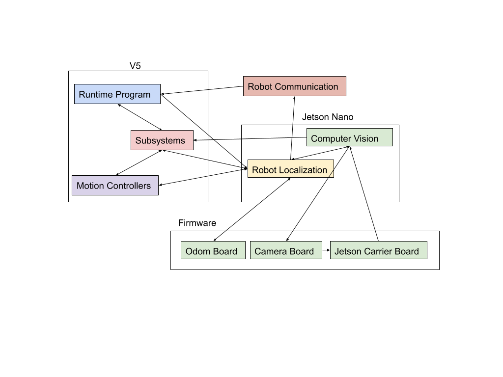
Author: Mira Teoli
Participants: Vince Song, Kieran Green, Ryan Jacobson, Cole Jowett, Mira
Teoli
A major aspect of gameplay is retrieving triballs so that we can use them to score goals on our opponent’s net. To do this, we must be able to identify the triballs using computer vision, distinguishing them from other objects within the view of multiple cameras. This is particularly important during the automated phase of the competition, and to help improve the accuracy of our robot localization.
The two defining characteristics we chose to focus on to identify the triballs were:
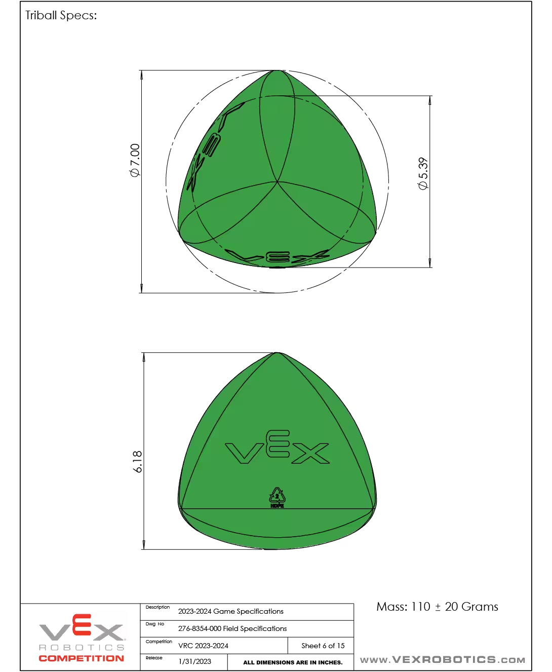
This is because the triballs are the only objects in the game that are coloured green, but there is a chance that the camera will capture objects outside the game zone that are green. To mitigate this, we check the aspect ratio (length divided by width), as it should be close to 1. Something else we considered (and may still implement), is only scanning for triballs below a certain height, as we always expect triballs we want to retrieve to be on the ground.
Calibration should be done prior to the start of gameplay to determine the range of colour that we expect the triballs to be in. This value will be in HSV. During gameplay, we will capture an image with the cameras, at a set interval, and create a mask over the image, making all pixels that fall within the calibrated colour range equal to 1, and all other pixels equal to 0. Then, we can conduct a DBSCAN, which essentially creates numbered labels for the objects found in the masked image based on the outlines. Next, we use a custom function (getSizes()) to return an array with the min/max x and y pixel values of all the objects found with DBSCAN. We can use this information to get the length and width of the objects and test the ratio of these to get the aspect ratio. If this aspect ratio is close to 1, then we consider this object a triball
Author: Mike Stefan
Participants: Lucas da Silva, Nicholas Lefterys, Evan Kreutzwiser, Nick
Mertin, Mike Stefan
Author: Nick Mertin
Participants: Michael Cassidy, Theo Lemay, Nick Mertin, Kieran Green,
Mike Stefan, Calvin Birch, Laura Cochrane
In this meeting, we discussed and decided on the QVEX software architecture plans for our first two competitions. The following software components will exist for QRC (Jan 20):
Since no external boards will be in use yet, all code will run on the V5. Localization will be done entirely with a conventional 3-tracking-wheel odometry setup, using existing code.
The following software components will exist for WV (Feb 16):
The firmware for each of the 3 boards will only be responsible for distributing data from the sensors attached to that board (or in the case of the Jetson carrier board, forwarding messages between the Jetson and the main comms bus). Computer vision, including the object tracking system, will run entirely on the Jetson; it will output final state estimates of all known objects and raw vision features (positions in pixel space) for localization landmarks. All other components will run on the V5, including robot localization; this ensures that no critical components are taken offline if the Jetson fails or reboots.
Author: Nick Mertin
Participants: Nick Mertin, Mike Stefan
We read into the documentation on the PIO block to figure out how to send UART signals from a PIO block. This lead to the refinement of the PIO code and the configuration settings needed to make it work. Below is a screen capture from a digital oscilloscope showing a transmission of the ASCII character ‘a’ using the custom PIO UART at 9600 baud.
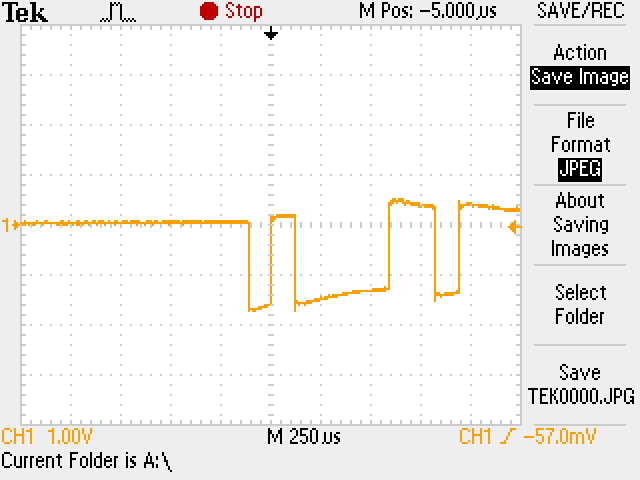
Author: Mike Stefan
Participants: Kieran Green, Mike Stefan, Calvin Birch, Laura Cochrane,
Kashan Rauf, Cole Jowett, Cooper Moses
A high quality autonomous routine contains three major components:
This meeting we developed our solution to the robot localization problem.
We evaluated a number of different possible odometery systens on a number of different attributes:
Our solution is to implement the 3 wheel odometery system as developed by VRC team 5225A as outlined in this document. This solution was choosen over other options since its trival to implement, we already had all of the required hardware and sensors, and its extremely accurate when tuned correctly.
This algorithm requires 3 external tracking wheels, which are placed
such that there are two paralelled wheels and one perpendicular similar
to this diagram: 
These external tracking wheels will be a 2.5in VEX IQ omni wheel with a
CUI AMT102-V encoder. This encoder was selected because they has an
adjustable ticks per revolution. This is an important factor due to
processing limitations of the V5. The V5 can only accumulate an encoder
with a TPR
The complete tracking wheel assembly looked like this: 
Using the data from these sensors we are able to accurately calculate
exactly how the robot moves in a small timestep. This is done by
approximating the robots motion as an arc over the timestep. This
algorithm is desgined to compute the change in position over an
infinitely small timestep, but due to computational limits on the v5 we
are running with a timestep of 10ms.
The following parameters are going to be used to notate physical
attributes of the robot and values calculated by the algorithm:
The algorithm consists of a few key steps:
Calculate
Calculate displacement
Rotate displacement to match global coordinate system
Update Pose
loop {
//read encoder
let l_ticks = self.left_encoder.read().unwrap();
let r_ticks = self.right_encoder.read().unwrap();
let s_ticks = self.back_encoder.read().unwrap();
//one tick is the robot constant of distance per tick
let l = one_tick * l_ticks as f64;
let r = one_tick * r_ticks as f64;
let s = one_tick * s_ticks as f64;
//calculate encoder changes
let dl = l-last_l;
let dr = r-last_r;
let ds = s-last_s;
//calculate theta
let da: Angle = ((dl - dr) / (self.config.dist_l + self.config.dist_r)).as_equiv();
let a = self.pose.a + da;
let hyp_x;
let hyp_y;
if da.is_zero() {
hyp_x = ds.as_equiv();
hyp_y = dr.as_equiv();
} else {
let i = da * 0.5;
let si2 = i.sin() * 2.0;
let radius_x = ds / da;
let radius_y = dr / da;
//calculate displacement
hyp_x = si2 * (radius_x + self.config.dist_s);
hyp_y = si2 * (radius_y + self.config.dist_r);
}
let a_halfway = a - da * 0.5;
let cos = a_halfway.cos();
let sin = a_halfway.sin();
//perform matrix rotation
self.pose.x += hyp_x * cos + hyp_y * sin;
self.pose.y += hyp_x * -sin + hyp_y * cos;
self.pose.a = a;
last_l = l;
last_r = r;
last_s = s;
self.broadcast.publish(OdomUpdate {pose:*self.pose, sensors: (l_ticks,r_ticks,s_ticks)});
select! {
_ = task.select() => continue,
_ = ctx.done() => break,
}
}Author: Kashan Rauf
Participants: Kashan Rauf
vex-rt currently has very little documentation, which can make it much more difficult for new members to get started since it takes longer to familiarize themselves with the usage of vex-rt. The solution to this problem will be the vex-rt book, a website which will contain a clear documentation that will outline and explain how to use vex-rt clearly. The documentation uses the rust book as a template since it is the same language used by vex-rt- making it more familiar for people who have knowledge of rust, and is hosted on Gitlab pages to easily deploy updates as soon as they are pushed. After successfully setting up the website, the current task is to write the actual documentation before public release. The documentation aims to cover the installation and set up stage, features of vex-rt such as macros, RTOS, and various modules that may be used, along with sample projects. Each feature’s documentation aims to include a general outline of capabilities, use-cases, and examples of practical applications. The vex-rt book is intended to be updated alongside vex-rt itself, and new features should be documented as they are developed.
Author: Nick Lefterys
Participants: Nicholas Lefterys, Michael Cassidy, Nick Mertin, Mike
Stefan
The existing communication protocol is designed to send as many packets as possible to ensure consistent communication and if a few packets are lost, the system is still able to function properly. This system has the upside of being quick to execute but if an important configuration packet is lost the system can break down and the run would fail. To prevent run failures, a priority packet system was deemed necessary to ensure that critical packets reach their intended target.
The goal of the priority packet system was to upgrade the existing comms protocol to ensure that a much higher percentage of packets reach their target. On top of ensuring high priority packets always reach their target, reducing the percentage of lost packets can improve the efficiency of the robot and accuracy of the robot control software.
When time to send data, the comms protocol gives the sending device a frame which contains the code that executes sending a packet. When the packet is sent to the target, the sender waits for acknowledgment that the target received the data. If the sender receives proper acknowledgement, the program has confirmed that the packet was successfully received. If the acknowledgement has not yet been received after a short time, the previous iteration of the program would carry on. To implement the priority system, a priority variable was added to the outbox which represents how many attempts the code should try to send the same packet before failure. After the creation of the frame to send the packet, the code enters a for loop where the same packet sending frame is given to the device, the packet is sent and the device waits for acknowledgement, if the packet was successfully received the loop breaks and the code continues, if the packet was not the loop will run again until either the packet is received or the maximum amount of attempts had been reached. The for-loop was chosen as a simple and effective way to implement resending packets. The higher the value of priority assigned to a packet, the more attempts the code will make, having a maximum number of attempts instead of trying until the message is received is to prevent locking the code in an infinite loop if for some reason such as hardware failure, the packet is impossible to be sent. Choosing a high number of priorities will result in a very high chance for success but for low priority packets, the default priority is assigned as 1 and the system will function just as it did before.
To test the program, the program is going be implemented on 2 V5 devices, one setup as the controller and one as a peripheral device, the testing program will tell the devices to send packets between one another and receive acknowledgement. To observe if the code is working, console logs are added into the code which state which during sending log the number of attempts the code has already had and the maximum number of attempts, it also logs after the loop if the final attempt was successful or if the packet was never received. Using these logs and the acknowledgement logs from the receiver, it is possible to determine if the system works as expected.
Author: Cole Jowett
Participants: Vince Song, Vincent Ho, Kieran Green, Ryan Jacobson, Cole
Jowett, Mira Teoli
It is useful to store the locations of relevant triballs and update them continuously. The first step in solving this issue is identifying how a triball will be stored. A triball state will be 6-dimensional and consist of the x, y, and z position and velocities of a triball. This allows the triball location to be recorded and predicted in the near future. The cameras around the robot will continuously take readings that have triballs in them. These readings are 3-dimensional, storing the x and y position within a camera and the radius in pixels (which can be used to approximate distance). Every time the cameras take a reading, a function is used that identifies where a known triball would be located in the camera feed. If a triball reading is found close to where the existing triball would be located in the camera, it is identified to be the same triball, and the triball location is updated using the UKF. If a triball is not seen in any of the camera feeds for a long period of time, it can be assumed that it has been picked up, scored, or manipulated in some other way and we can stop tracking that triball. If a triball reading appears that does not align with a tracked triball, it can be identified as a new triball and its state can be estimated and stored.
Author: Kieran Green
Participants: Vince Song, Kieran Green, Ryan Jacobson, Cole Jowett, Mira
Teoli, Ben Probst
One of the landmarks we thought would be good to know was the goal poles since they would be visible from any part of the field. This would allow us to have a constant spot on the field that we can compare to that can be fully obscured by another robot.
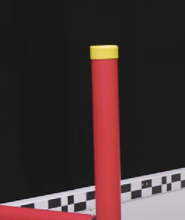
We started by trying to figure out how we would identify the goal based on any unique parts of it. This proved to be more difficult than expected since red and blue are very common colours during a VEX tournament, and the goal could appear in many different orientations that could appear as one or two different objects on our cameras. This made us realize that we would need to change how we would find the goals. We decided instead we would look for the yellow caps on the top since those would be much easier to detect since they would be the only yellow game object on the field. If it detects a yellow object outside the field of similar size we could cross-check it by checking if there is blue or red right underneath the yellow cap. This would make it so that there would be very few scenarios where we would falsely identify another object as the goal. Our last safety measure will be to make sure that both of the climbing pole tops are within an acceptable distance from each other and are around where we would expect them to be.
Author: Kieran Green
Participants: Vince Song, Vincent Ho, Kieran Green, Ryan Jacobson, Cole
Jowett, Mira Teoli, Ben Probst, Justin Abuyuan
Author: Calvin Birch
Participants: Kieran Green, Calvin Birch, Anders von Enckevort, Ryan
Jacobson
Discussed timeline and reviewed everyone’s progress with their respective subsystems.
Author: Calvin Birch
Participants: Evan Kreutzwiser, Kieran Green, Calvin Birch, Ryan
Jacobson
Finishing all subsystems.
Author: Ruby Wang
Participants: Kieran Green
For our implementation of this intake controller, we employed a state machine starting in the default “Idle” state. States like “Idle” and “Outtake” were straightforward, involving simple motor speed adjustments. In the “Auto” state, we introduced a loop that monitored the average velocity of the motor. To prevent false triggers of the “Jammed” state that measures average when the average velocity of the motors is under a threshold, indicating that an object is impeding the rollers. We added conditions to account for initial startup or transitions from outtaking to intaking. Through testing, we determined that the intake, when running, averaged an angular velocity of approximately 210 rpm. To optimize performance, we set a threshold of 127 rpm for the “up to speed” condition before checking for potential jams. In the “Jammed” state, the intake reverses for one second before returning to the “Auto” state.
The current implementation of the jammed function occasionally encounters issues when detecting jams. Our next steps are to improve the reliability and effectiveness of jam detection, by refining the algorithms or mechanisms responsible for identifying and responding to jam conditions.
Author: Ryan Jacobson
Participants: Calvin Birch, Ruby Wang
The goal is to use a state machine in Rust to accurately and consistently operate the linear puncher of the robot.
There linear puncher consists of 3 states: ready to fire, fire, and reset. The ready to fire state stops the motors of the linear puncher in a position where if rotated back any further, it would hit a slip gear and fire. This state functions as an idle state, so the robot will be immediately capable of firing once loaded. The robot will remain in the ready to fire state until instructed to enter the fire state. The fire state will bring the puncher back a bit further from the ready to fire position until it hits the slip gear. This will cause the linear puncher to launch the triball forward. After firing, this state will transition into the reset state. The reset state brings the linear puncher backwards into the ready to fire position. Once in this position, it transitions into the ready to fire state.
The initial next steps involve testing the linear puncher and fixing any issues to ensure it works correctly during the competition. Then after the first competition it depends on if a new shooter mechanism is introduced. If the linear puncher remains the same throughout the season, then only small improvements to performance and possibly some new features will be required. If a new shooter system is created, then new code will need to be written specifically for the new shooter, and then tested and improved over time.
Author: Laura Cochrane
Participants: Michael Cassidy, Kieran Green, Mike Stefan, Laura
Cochrane, Cole Jowett, Steve Calles
Author: Laura Cochrane
Participants: Michael Cassidy, Theo Lemay, Kieran Green, Laura Cochrane,
Cole Jowett
Author: Mike Stefan
Participants: Lucas da Silva, Nicholas Lefterys, Michael Cassidy, Severn
Lortie, Mike Stefan
The main job of this board is to collect the data from all sensors and collect them into a singular packet which can be sent over the main comms bus to the v5, where the odometery calculations will use this data. The initial plan for this board was to collect the data and perform the computations locally, then only transmit the final pose estimate over the comms bus. We decided to change this as a safety measure. We want as much of our computations on the V5 as possible to protect against brownouts and packet losses. By performing the computations on the V5, we can ensure that the result will be calculated regardless of the power or connection status of the side processors.
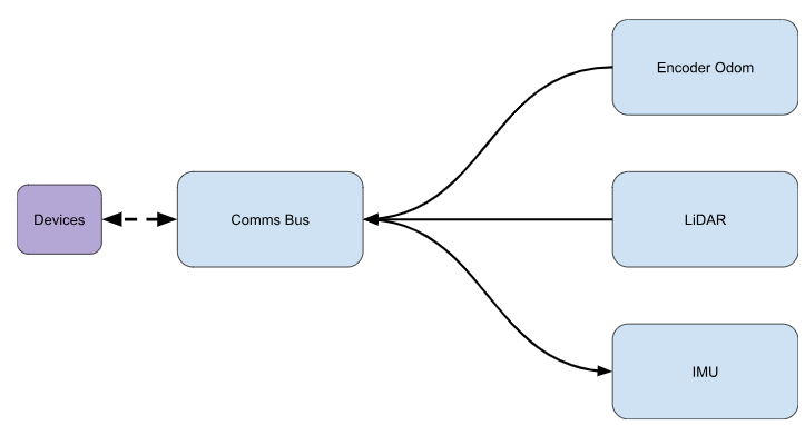
Each box represents a separate task, which the RTOS will schedule as we see fit. Each sensor data will have a shared memory block with the Comms Bus which allows the sensors to safely publish their data to the bus, which will be periodically compiled into a singular packet by the Comms Bus task which is then sent over the Comms bus to all other devices. This transmission ideally should happen at a regular time interval, so it should be sent whether it has new data from every sensor or not.
The IMU’s task will poll the sensor’s I2C bus and use that data with the AHRS algorithm to calculate a heading estimate. For proper operation, the IMU will also need a calibration task that is started upon board power-up and at the request of an external device over the Comms Bus. During this calibration period, the robot should be stationary so it must send a high-priority acknowledgement to the robot to ensure it is stationary. If the robot is not stationary during this calibration, all data produced by the sensor should be ignored until we can calibrate. This recalibration will likely be impossible if the board is temporarily powered down midmatch, and this fail state should be considered in the final Pose estimate. During this calibration, it must follow the operating mode config steps outlined in Chapter 6 of the datasheet. We will also want to perform the 3-second calibration required by the AHRS algorithm.
The encoder accumulation does not need to be considered on our task list, as it must happen in the PIO block of the RP2040. The PIO block allows a small amount of assembly to run separately from the main Cortex-M0, allowing us to quickly perform fast read/write operations without using CPU clock cycles. This means the only encoder clock cycles we will use are periodically reading the PIO memory queue, and calculating a Pose estimate using the standard 3-wheel odom calculation described in this document. If we decide to perform all odom calculations on the V5, this step will be excluded and the Comms Bus will read from the PIO memory queue when generating the packets.
The LiDAR task will have to gather the data from a full rotation of the scanning unit, process it into a nice format to be published for the comms bus, and eventually send it to the other devices. This process should happen at a regular time interval.
Author: Vince Song
Participants: Vince Song, Kieran Green
Author: Lucas da Silva
Participants: Lucas da Silva, Mike Stefan
The project is to create a timer module which creates generic timers, Instants and Durations regardless of the chip choice, and where that information that is needed from the chip can be passed at initialization.
The goals of the project include:
Author: Nick Lefterys
Participants: Nicholas Lefterys, Michael Cassidy, Nick Mertin, Mike
Stefan
To test the program two V5s, were connected to each other as show below and instructed to communicate with one another, with one V5 following the communication protocol of a peripheral Odom board and one acting as a regular V5. The test first consisted of having the V5s send packets back and forth, showing that the sending and receiving of packets worked as expected. Then the V5s were disconnected and told to send packets back and forth again. This time the logs showed that the packet was sent but not received by the other V5, the V5 would then retry sending the packet the expected number of times based on the value of priority before giving up. The system functioned as expected and will be implemented at QRC.
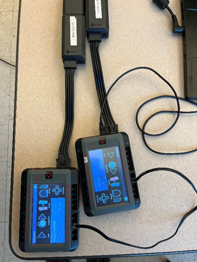
Author: Kashan Rauf
Participants: Kashan Rauf
Create a comprehensive set of states that accurately control the climber mechanisms, remaining faithful to the design in order to maximize ease of use and effectiveness.
The climber has 5 states, Idle, Ready, Deploy, Climbing, and Braking. The robot starts in the Idle state and proceeds to the Ready state, where it awaits a specific controller input (L1+R1) before attempting to activate in the Deploy state. If the attempt to deploy fails, the climber returns to the Ready state to try again, but if it succeeds, the robot will transition to the Climbing state. In the Climbing state, the motors are controlled by the Y channel of the right analog stick, and climb at a speed based on the given input, the robot will remain in this state until one of two events:
In either of these cases, the climber will transition to the Braking state, where it will hold itself in place.
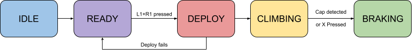
No changes to the current solution are planned unless changes to the climber mechanism are made.
Author: Cole Jowett
Participants: Michael Cassidy, Nick Mertin, Mike Stefan, Cole Jowett
This project was started after trying to create a velocity controller for the drivetrain to allow for superior path following abilities. Creating the PID controller turned out to be more difficult than expected. The system became quickly uncontrollable, likely due to latency and noise in sensor readings. An image of one attempt at a PID controller is shown below - the controller used a large integral term and a small derivative term meaning it would not respond well to disturbances. The displayed test reached the setpoint in around 400 ms.
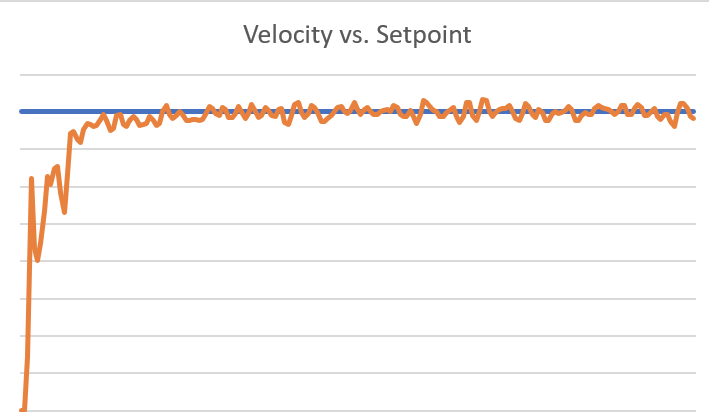
To bypass this issue, we opted to use less feedback control and create a feedforward model of the drivetrain. Rather than doing this manually, we wrote a series of tests which allows the drivetrain to be modelled in a few minutes. This is convenient as the drivetrain should be remodelled when mechanical changes occur to the robot that may change weight or friction in the drivetrain. The model of the drivetrain is relatively simple. It consists of three gains. The first gain - “kS” - is the voltage applied to the drivetrain to overcome resistance in the drivetrain and start moving. The second gain - “kV” - relates to the amount of voltage to apply to overcome drag forces and kinetic friction in the mechanisms. The third gain - “kA” - tells us how much voltage is needed to accelerate the robot. The full equation can be given by the following:
V_applied = kS * sgn(v) + kV * v + kA * a
By finding the correct gains we can control the drivetrain with minimal feedback control or no feedback control.
The feedforward gains have varying difficulty to measure through testing. kS is very easy to determine - it is the minimum voltage required for the drivetrain to start moving. We simply increase the voltage until we see the encoders starting to change angle. We can find both kS and kV by setting the acceleration of the robot to zero, although this is unreasonable to do in reality. to find kS and kV we perform a quasistatic test - which is a test where the drivetrain accelerates very slowly. This allows us to form a plot which linearly relates the voltage to the velocity with negligible acceleration. The x intercept of the voltage versus velocity plot will be kS, and the slope will be the reciprocal of kV. A graph of one of these tests shows the roughly linear relationship:
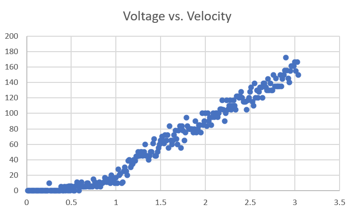
We can write a quasistatic test that ramps the voltage slowly and takes performs simple linear regression on the test data. By taking a few trials and averaging the result we can get fairly good data even with the noisy velocity readings. We can verify the results of these tests by seeing how well the robot can now hold a velocity setpoint.
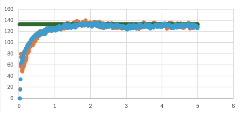
This test shows that the robot can hold a velocity setpoint quite well. This means we had good kS and kV values for the drivetrain. The issue is that the drivetrain takes a second to accelerate to the desired speed as we are performing this test with a kA value of zero.
It is much more difficult to determine the kA value than kS or kV. While the robot can have velocity without acceleration for a extended period of time, it cannot have acceleration with no velocity for an extended period of time. This means that we cannot eliminate any terms from the equation. To perform the dynamic test, we need to take measurements of both acceleration and velocity. Once we have applied a constant voltage with a known kS, kV, velocity, and acceleration, these can all be plugged into the feedforward equation to solve for kA. Multiple of these tests may want to be performed because they last much shorter than the quasistatic test. While the robot can move at a slow speed for more than 20 seconds, we cannot accelerate the robot for more than a few seconds before it reaches its maximum speed. The last graph supplied shows a constant voltage applied to the robot and it only accelerates for about a second.
Now that we have determined all three of the feedforward gains, the feedforward equation becomes very useful. It is a great way to control the velocity of the robot by determining an input voltage. It can also be used to estimate the acceleration of the robot given the applied voltage, which can be a useful tool during robot localization.
Author: Kieran Green
Participants: Kieran Green, Mike Stefan, Laura Cochrane, Cole Jowett,
John Williamson
For our second competition, we wanted to improve our current autons to make them more consistent and faster. We updated the robots so they can now go underneath the climbing poles on the side of the field. This greatly improved both the consistency of our autons and our speed. This also opened up the option for a different winpoint auto than the one that was run at our first competition, which would split the work between the two robots more evenly and not have most of our winpoint rely on one robot. The new route picked can be seen below:
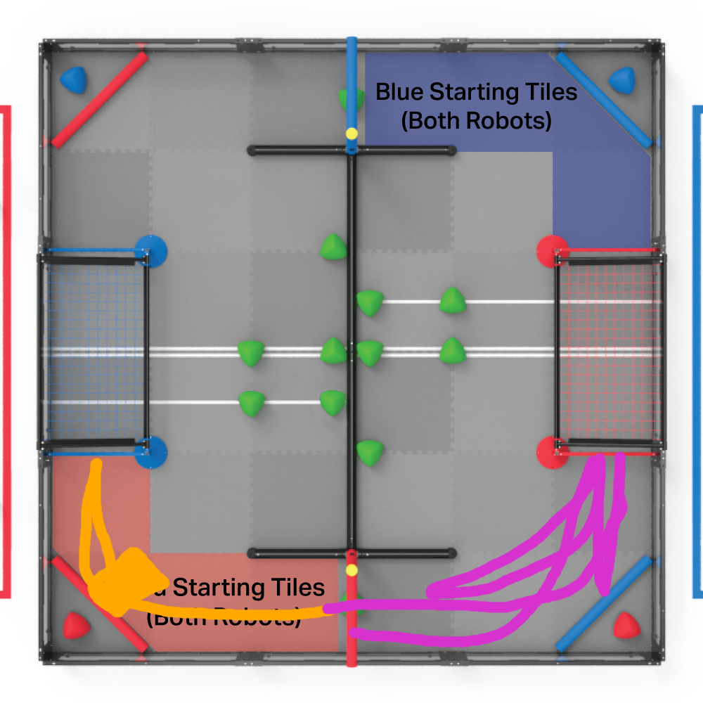
The orange line is the 24” robot; this robot starts by shooting its preload and then taking and scoring the alliance triball into the other team’s goal. From there, it goes back and shoots the 10 match load triballs available in auton. After it’s done shooting, it goes over and touches the climbing pole. Since our match load shooting macro is not a set time, based on when it sees the ball placed in the match load, making it have a variable time length, we added a timeout so that no matter what, the robot will touch the climbing bar. We chose the 24” robot to do this part of the auton since the climbing hooks attached to the robot will sometimes turn the robot slightly when going under the bar. Well this will not ruin our program since we have angle correction, it can cause it to be slower.
The pink line is the 15” robot. This robot intakes the triball underneath the climbing pole and then scores it. It then backs up and picks up the alliance triball and scores it. Around this time, the 24” robot has started shooting balls over near the 15” robot. The 15” will then back up close to the climbing pole and wait before pushing the piled-up triballs into the goal before returning and touching the climbing pole.
Author: Severn Lortie
Participants: Lucas da Silva, Nicholas Lefterys, Michael Cassidy, Evan
Kreutzwiser, Severn Lortie, Nick Mertin, Mike Stefan
The PIO blocks on the RaspberryPi 2040 chip are small circuits that are useful for fast, IO intensive, parallel programs. Software is written for them using a simple (just 9 instructions!) assembly language. However, testing PIO programs is difficult. That’s because there is limited debugging facility on the chip. That is where emulation becomes a real convenience for development. Fortunately, a great emulator has already been written and is readily available online. It is called the RP 2040 PIO Emulator and it was written by Jürgen Reuter. This document provides an easy to understand tutorial on installation and usage. The complete guide (which is more complicated) can be found here: https://rp2040pio-docs.readthedocs.io/en/latest/introduction.html
I will now try to explain the basics of the PIO circuit. I won’t be able to cover everything. A wonderful resource is chapter 3 of the datasheet. I recreate some of their diagrams here as well.
There are two identical PIO (Parallel Input and Output) blocks on the RP2040 chip. PIOs are great for running tiny, low-level code that manages input and output to and from the GPIO. Without using a PIO, we would need to steal precious CPU resources to handle these routines. Instead, we write a program once, load it into the PIO, and it chugs along happily with little CPU interference until data is ready.
A single PIO block is composed of 4 State Machines (SMs), 8 First In First Out (FIFO) registers, some instruction memory, and circuitry for managing GPIO interaction (pictured above). Let’s start by understanding the FIFO registers. The FIFO registers are the way the PIO receives and sends data to/from the CPU. The FIFOs are labeled from the perspective of the CPU. The RX FIFO is for data the PIO is sending the system, and the TX FIFO is for data the system is sending the PIO.
There are 4 identical state machines in the PIO. These state machines are only able to execute simple instructions, like shifting data or reading from a GPIO pin. They cannot do math, manipulate data in any extensive way, or do most other things CPUs can do. They are intended mainly for reading and writing data to and from the FIFOs and GPIO.
Each state machine has access to the same GPIO and instruction memory (see above). The state machines can all run the same program, or each can run a separate program. This is achieved by pointing their Program Counter (PC) registers at different points in instruction memory. For example, SM 0 (State Machine 0) could run a program starting at memory address 0, whereas SM 1 could run a program starting at memory address 10. Or, both could run a program at memory address 16.
The last pieces of the PIO I will discuss are the Input Shift Register (ISR) and the Output Shift Register (OSR). As pictured above, the ISR is for moving data from the GPIO to the RX FIFO. The OSR is for moving data from the TX FIFO to the pins (or internal scratch registers X and Y). These registers are used a lot in programming the PIO, so it’s important to be familiar with them. Now, let us look at an example program to understand some basics of the PIO assembly language (pioasm).
1 .program squarewave
2 set pindirs, 1 ; Set pin to output
3 again:
4 set pins, 1 [1] ; Drive pin high and then delay for one cycle
5 set pins, 0 ; Drive pin low
6 jmp again ; Set PC to label `again`The first instruction on line 1 is for the assembler, it lets it know the name of the project. The second line has the effect, in this specific case, of setting the direction of GPIO 0 to output. The first word, set, indicates we are going to set a destination with an immediate value. E.g., a value that is encoded in the instruction itself (in this case the number 1). The second word, pindirs, is the destination for the set instruction. Here, we are setting the pin directions of the GPIO. The last part of the instruction, the number 1, indicates we are setting the pin to an output (0 for input).
You may have noticed that the instruction on line 2 is missing information. What GPIO pin directions will actually be set? You can’t tell from just the instruction. This is because, before the program is loaded in, the programmer must specify the pin mappings for the set instruction. This is done by writing to special memory locations on the RP2040 that indicate the set instructions base and count. The base is the starting pin, for example GPIO 0. The count is the number of pins that will be set, sequentially from that point. Then, the set instruction writes an immediate value to the GPIO mapping hardware, which uses that value to decide the output values on the GPIO. For example, say the set base is GPIO 2 and the count is 3. The instruction set pindirs, 0b111 will set GPIO 2 to 5 to be outputs. The instruction set pindirs, 0b1111111 would have the same effect since the count is 3.
Instruction 3 marks a point in the code that can be later returned to with the jmp instruction. Instruction 4 uses the set operation to write GPIO 0 high - since we used pins as the destination. Again, we know it does that because we preconfigured the GPIO mappings. Additionally, it delays for an extra clock cycle with the syntax [1]. This is a major advantage of the PIO. Every instruction executes in exactly 1 clock cycle. To perfect timings, additional delays can be added to instructions with the [delay] syntax. Instruction 5 does the same except sets the GPIO to 0. Instruction 6 returns back to the again: label.
With a hold on the basics of the PIOs function, let’s dive into the emulator software.
Requirements:
git clone [email protected]:soundpaint/rp2040pio.git
cd rp2040pio
make all
Inside the /jar directory you will find many .jar files. Each of these is a part of the emulator and they all offer useful functionality. For the purposes of this tutorial, we will focus on three of the programs:
You generally start the server and then leave it alone, running in the background. Your main work will be done interfacing with the monitor CLI.
First, make sure you are in the rp2040pio/jar directory. Then, run the command:
java -jar rp2040pio_server.jar
This will start the emulator server. Open a new terminal tab and run the command:
java -jar rp2040pio_monitor.jar
This will open the monitor CLI. You can type help for a list of available commands. To illustrate some important functionality of the emulator, let’s load in the squarewave program that was analyzed in the previous section. First, reset the state of the PIO with the reset command. Fortunately, that program comes pre-packaged with the emulation software as an example. To load the instructions into PIO 0’s memory (remember there are two identical PIOs on the RP2040), type load –example squarewave. To see the memory of the PIO, which has now been loaded with the squarewave program, type unassemble. You should be able to see the instructions we went over previously now in the memory of PIO 0!
We can’t run the program quite yet. We need to configure the GPIO pins and GPIO mappings. Fortunately, the monitor program comes with some handy commands to do this. Type pinctrl -h. Take note of the –-set-count and —-set-base options. These let us configure the set instructions base and count options for easy mapping. We want to produce the squarewave on GPIO 0, so let’s use the command pinctrl –set-base 0 –set-count 1.
Next, we need to tell the RP2040 to connect GPIO 0 to PIO 0. This can be done with the command gpio –gpio 0 –pio 0 –init. Now, an SM will be chosen to execute the program. Let’s use SM 0. To enable SM 0 on PIO 0, use the command sm –sm 0 –pio 0 –enable true. We are now ready to run the program! A loaded program can be single-stepped with the trace command. This command will execute a single clock cycle. Run the trace command twice. Now, to see the effect this had on the GPIO, type gpio. That will show the direction change (from green for input to red for output) and the level change (from 0 to 1). You can also type unassemble at any time to see the currently executing instruction. This alone is extremely useful for debugging. However, for complex programs, a visual representation of the PIOs state is easier to inspect.
To view a diagram of the PIOs state, open a new terminal tab and type
java -jar rp2040pio_diagram.jar.
This will open the diagram creator applet. You should see something like below:
Press the
button to execute a single clock cycle. Here is what you should see after 9 clicks:
Wow! The squarewave program works! As you can see, GPIO 0 is alternating on and off every two cycles. What is nice about this view is that you can see the instruction register along with the waveforms. The grayed out portions of the signal indicate the PIO waiting an extra clock cycle (set pins, 1 [1]).
It is quite cumbersome to run all the commands needed to setup the PIO every time you want to debug a program. If we were using an RP2040 and the accompanying SDK, we could write the setup instructions in code. However, since the emulator is a command line application, we do not have this convenience. That is why the Monitor program provides a basic scripting facility in the form of Monitor Scripts. Monitor Scripts are just text files with Monitor CLI instructions every line. These scripts do all the work of initializing the PIO and let us focus on debugging the program.
To demonstrate how scripts work, let’s look at the script I wrote to initialize my UART RX program. I have reproduced it below:
#### This script is responsible for setting up the state machine, loading the code into
#### PIO memory, and then kicking off execution.
#### Fully reset the state of the PIO
reset
#### Set the RX line initially high
gpio --set --gpio 0
#### Configure the rx pin (0) to be an input
gpio --gpio 0 --pio 0 --disable
#### The uart_rx algo. uses the rx pin as a jmp selector. If it is not 1 at the end of a data frame, it discards the sent data
pinctrl --jmp-pin 0
#### We need to specify that the IN instruction maps to pin 0
pinctrl --in-base 0
#### Connect the PIO to GPIO 0
gpio --pio=0 --gpio=0 --init
#### FIFO setup is next
#### 1. Turn off auto push for the ISR
fifo --auto false --rx
#### 2. Join the RX FIFO with the TX FIFO for 8X32 capacity in TX FIFO
fifo --join --tx
#### 3. Change the ISR to shift to the right (since uart is LSB first)
fifo --shift-right --rx
#### Enable the PIO to use GPIO 0
gpio --pio=0 --gpio=0 --init
#### Set the clock divisor to 1. We are going to assume for the purposes of debugging that we are running at a clock speed of
#### 8 X the baud rate.
clock --divider 1
#### Now we can load the code
enter -a 0 -v 0x2020 # wait 0 pin 0 ; waiting for RX to go low (e.g. start bit)
enter -a 1 -v 0xea27 # set x, 7 [10] ; preload the loop counter and delay until in middle of next data bit
#### loop:
enter -a 2 -v 0x4001 # in pins, 1 ; load a bit from the RX pin
enter -a 3 -v 0x0642 # jmp x-- bitloop [6] ; read the next 8 data bits
enter -a 4 -v 0x00c8 # jmp pin end ; if the jmp pin is 1 then the data has been correctly framed. Wait for next frame
enter -a 5 -v 0xc014 # irq 4 rel ; set a irq flag to let cpu know data was bad
enter -a 6 -v 0x20a0 # wait 1 pin 0 ; wait for the line to return to high to signal end of transmission
enter -a 7 -v 0x0000 # jmp start ; wait for line to go low and try to receive the next frame
#### end:
enter -a 8 -v 0x8020 # push ; push data from IRQ to RX FIFO for CPU use
#### Enable PIO 0, state machine 0 to run this program
sm --pio=0 --sm=0 --enable=true
QuitAs you can see from the above script, it does similar setup tasks as the squarewave example, with a couple differences. First, the script configures the pin direction of GPIO 0 to be an input with gpio –gpio 0 –pio 0 –disable. In the squarewave example, we achieved this using the set pindirs instruction. The approaches are equivalent. Second, this script loads the program into instruction memory with the enter command. You can achieve a similar result if you already have the HEX file by using the load -f command.
There are two approaches to testing PIO programs that need to use external data. The first involves writing a monitor script that runs in parallel with the program and waits for instruction cycle events to assert values onto the input GPIO pins. This way is rather obtuse, but could come in handy for highly time sensitive PIO programs. For the sake of time, I do not cover how to do this. If you want to debug that way, refer to the “Interfacing With External Data” part of the guide.
The method for testing the UART_RX program here will be much simpler. The commands gpio –gpio 0 –set and gpio –gpio 0 –clear can be used to assert 1 or 0 on the RX GPIO. If the program works correctly, the values will appear in the ISR and then the RX FIFO. Begin by downloading the UART_RX script file here. Then, place it somewhere convenient and run the command script –file <path-to-uart_rx.mon> –dry-run false. This will load and run the script file. Now, start to single step the program with the trace command (or use the Diagram Creator applet as I do here). As you can see from the waveform below, the program is waiting for the start bit on GPIO 0. Note that GPIO 0 in the waveform represents only the values the PIO outputs, not data asserted by the Monitor program.
So, let’s set GPIO 0 to 0 and see if the program reacts accordingly. Run the command gpio –gpio 0 –clear. Here’s the resultant waveform:
Look at that! The program stopped waiting. The set instruction after the wait instruction sets the loop counter to 7. This program implements standard UART which receives frames of 8 bits at a time. So, it needs to preload a scratch register with a loop counter to track the number of data bits it has received thus far. Now, let’s go ahead and set GPIO 0 to 1 and see if that value is reflected in the PIO’s registers. Run the command gpio –gpio 0 –set and trace around 10 times. Now, inspect the register values with the command registers. What you should see is that the ISR has the HEX value 80000000 or in binary that is 1000 followed by a bunch of 0s. So, the 1 we asserted on GPIO 0 got shifted into the ISR from the left (the left shift is necessary since UART is LSB first). Looks like the program is working as expected!
Author: Cole Jowett
Participants:
One challenge we face in the VEX Robotics competition is the need for the robot to autonomously follow efficient and fast paths on the field. Although simple algorithms such as PID controllers based on robot position may work well enough to make some autonomous routines, being able to follow well defined smooth curves at very high speeds provides a great advantage during the autonomous period.
For our purposes a “path” will consist of several pieces of
information, a geometric spline with the robot will follow, a velocity
profile which tells the robot the speed it should be travelling to
follow the path, and turning commands which tell the robots how to turn
to follow the curve. It makes sense to generate the path using a Beizer
spline - or a series of bezier curves which are connected in a
continuous fashion. A single bezier curve consists of 4 points, a start
point, two control points, and an end point. The robot will pass through
the start and end points, but may not pass through the control points,
which primarily serve to help shape the path. These points are denoted
or in the matrix form
For the purposes of creating a continuous spline, the start point of any curve will be the end point of the last curve. As well as this, it is a requirement that any of these connecting points are colinear and equidistant to the control points before and after them:
 An image of a bezier spline on the Over Under field - the endpoints
of individual bezier curves can be seen in the middle of two control
points.
An image of a bezier spline on the Over Under field - the endpoints
of individual bezier curves can be seen in the middle of two control
points.
Now that we know how we will find the geometry of the curve, we need to find out how to make a velocity profile of the curve. We can choose how to sample points along the curve. We can sample points along the curve at equal time intervals or at equal distance intervals. For our purposes, we will sample points at an equal time interval. This is because it is easier to find the time elapsed since the start of a path than it is to find the distance along the path. For example - how would we find the distance along the path of a robot which has slightly deviated from the path? We could find the nearest point on the path but this would be computationally expensive and would not work on paths that overlap themselves. Now that we have decided to sample the points based on time we can continue to generate a velocity profile.
To generate the velocity profile we need to consider several kinematic limits. These kinematic limits are limits we have applied on the robot to make sure that the path is physically possible for the robot to follow. Making the kinematic limits stricter will generally increase the amount of time it takes to traverse the path but make the path easier to follow and smoother.
The first limit that is necessary is the tangential acceleration limit. Without giving any tangential acceleration limit the robot would attempt to instantly accelerate to its maximum speed. This is obviously not possible and the robot will fall behind the desired location along the path.
The second limit that is necessary is the velocity limit. Without the velocity limit the robot attempt to accelerate past its top speed, falling far behind the path.
The third limit is the radial acceleration limit. Although this limit is not 100% necessary to the functionality of the path generator, it can be a useful tool. This limit allows the robot to slow down when taking tight turns.
Implementing these three limits into the path generator is not a
trivial task. It is important that the robot is following all three
kinematic limits at all times, so there are some edge cases that need to
be accounted for. For example, if the robot is driving at full speed,
and it suddenly needs to take a sharp turn, the velocity of the robot
following along the path will decrease rapidly. This will be a violation
of the tangential acceleration limit. We need to tell the robot to slow
down before it reaches a turn. We also need to tell the robot to slow
down to a complete stop at the end of the path. For this reason, we have
written a recursive function that travels backwards through the velocity
profile and reduces the past velocity to follow the tangential
acceleration limit. However, this also leads to unforeseen issues. The
implementation at the time of writing this function involved keeping the
track of the distance travelled in a variable, and adding
To generate the full velocity profile of a robot, we need to know the length of the full path. We continue taking samples and extending the velocity profile until we observe that our elapsed distance exceeds this value. To find the arc length of a parametric function we use the formula
With some functions, such as helices, we can use this formula along with some trigonometric identities to find an elegant formula for the arc length of the function. Unfortunately, we do not have this luxury with the cubic bezier curve. When we apply the arc length formula to a cubic bezier curve we end up with an elliptic integral. This means there is no closed form solution to the integral and we must estimate it computationally. For now we will do this with a basic Riemann Sum of 100 intervals, although this is an expensive computation.
Now that we have a geometric shape which we will follow, and a
velocity profile which we will follow, we can begin to take the samples.
Each sample should contain all the information the robot needs to know
to follow the path. For an open loop control system this would be the
forward velocity and turning rate command, denoted
The values are calculated in many different ways. We initially have
only two known values: the velocity command from the velocity profile
along the path, and the distance travelled along the path. This means we
must solve for the four values
To find the values of
To find the turning rate of the robot we need to know the tangential
velocity of the robot,
Now that the radius of the circle is known, we can use the
relationship
Now that we have found our location along the curve in terms of the
parameter
Finding
atan2(y, x), which can properly return the angle to a point
in any quadrant of the coordinate plane, unlike the mathematical
Initial testing of the path generation algorithm was not promising. The paths took well over 10 seconds to generate on laptops which compute the paths far quicker than a V5 Brain would. Although this can be bypassed by generating autonomous paths at compile-time and uploading them as a part of the binary to the brain, this eliminates the option of on-the-fly path generation. Clearly something has to change within the path generation algorithm.
Although functions involving bezier math were initially written in the matrix form of a bezier curve for ease of modification (taking the derivative in this form only requires deriving the four values in the leftmost matrix), testing showed that this was slower than just evaluating the polynomial form of the bezier curve.
By far the most blatant waste of computing time in this path
generation program is the method for finding the arc length of a bezier
curve. Especially with the inefficient method of using the binary search
requiring evaluating the length of a bezier curve 8-10 times to find one
To understand how De Casteljau’s algorithm works we first need to one
interpretation about how a bezier curve works. The bezier curve is based
on a linear interpolation, which interpolates between two points,
applying weight based on the parameter
The point would start at
This pattern continues forever, and allows one to evaluate and degree
of bezier curve - but how does this help us find the length of a bezier
curve. This method of evaluating bezier curves shows us that there are
many intermediate points involved in this calculation, and we can use
these to our advantage. We can actually split a bezier curve into
multiple bezier curves of the sample degree by using this form. A
quadratic bezier curve consists of three points, and evaluating it
consists of two layers of
Now that we have the ability to split bezier curves, how will we
apply this to find the arc length of a bezier curve? One thing we can do
is compare the length of the control net to the distance between the
endpoints. The control net consists of the three line segments formed by
the point of the bezier curve:
Considering the fact that the Arc Length function still takes a
majority of the compute time to generate a path, we should aim to use
this function as effectively as possible. The main issue is that the Arc
Length function is being called about 10 times during a binary search
while finding the value of
Applying these optimizations to the path generation algorithms, along with some other small changes along the way greatly increased the efficiency of the program. A path can generally be generated in about 20ms on the same hardware it used to take 20 seconds on, which is 1000x as fast! Although these results are great compared to the initial tests of path generation, there is still more work to do. The V5 Brain can still take a few hundred milliseconds to calculate a long path, which can cause a visible pause between when a robot is commanded to follow a live generated path and when it starts moving. There is, however, still room to improve the path generation, and it will likely be viable for on-the-fly path generation in the near future. Some improvements that could be made involve generating the path in segments, allowing the robot to start following the path while it is generating. There could also likely be more overlap between the generation of the geometric path and the velocity profile to reduce reduntant calculations.
Author: Cole Jowett
Participants: Michael Cassidy, Theo Lemay, Nick Mertin, Mike Stefan,
Laura Cochrane, Cole Jowett
After removing the 3-wheel odometry setup it becomes necessary to implement an alternative odometry system. It is difficult, but possible to implement a system that uses less accurate sensors but achieves a higher accuracy and allows access to more information. This system can also requires minimal modification to allow for more sensor data to be added to the system and accuracy to improve further.
The Kalman filter is an algorithm which tracks a state along with an associated uncertainty. The algorithm allows us to combine several measurements with associated uncertainties along with our previously known state to update our knowledge of the state. This means we can track things that have noisy sensor values, such as in the example below
One system which we can use as an example to apply the Kalman filter
is a motor with an encoder measuring velocity on it. The mean of the
motor state, denoted
Our state also has an associated covariance matrix, denoted
The unscented Kalman filter, also known as the UKF, is a modified version of the Kalman filter which allows it to be used for highly nonlinear systems. In our case we have a highly nonlinear model, with the parts of the robot state depending on complex physical models of the real world. It does this using a tool called the unscented transform.
The unscented transform is the basis of the UKF, and is what allows
it to be used for nonlinear systems. It allows a probability
distribution to be propogated through a nonlinear function by creating a
series of points called sigma points. These sigma points are points that
are near the mean, and based on the uncertianty. We use
After putting these sigma points through a nonlinear function, we can find the mean and covariance of the output points. This allows us to estimate a new mean and covariance. We use this transform in both the update and predict step of the UKF.
The unscented transform allows us to perform the update step in what may feel like a “reversed” manner at first. Instead of trying to calculate the state using the measurement, we calculate the measurement from the state. This makes sense as most measurements tell us not nearly enough information to estimate the entire state. What we do is create a function, say
Which estimates our measurement given our state and noise- in this case assuming our measurement and noise are one-dimensional. First we need to calculate all of the sigma points. In this case, we will append the noise matrix to the state covariance as follows (with R being the noise):
and we append zeros to the end of the state matrix (assuming the process noise is centered around the mean and does not skew in one direction):
We calculate the sigma points with these new mean and covariance. We
then calculate the result of
More generally,
It can be noted that in the previous example
Recall that the job of the predict function is to propogate the state
forwards based on itself and incorporate the process noise. To begin the
predict step we will first create a new mean and covariance matrix based
on the process noise. The covariance and mean will be created in the
same fashion as they are during the update function, then sigma points
will be created. Note that this is the reason that a generic
unscented_transform(...) function is implemented in code
that is used by both the predict and update steps. After we have created
the sigma points, we need to put them through
A basic function that assumes that the state stays the same may look something like this:
f_predict(x: Vector4<f64>) {
return matrix![x[0] + x[2]; x[1] + x[3]];
}We can also write a more complicated relationship if our state
variables depend on eachother. For the purpose of our example, lets say
our state is of the form
f_predict(x: Vector4<f64>) {
let noisy_state matrix![x[0] + x[2]; x[1] + x[3]];
return matrix![noisy_state[0] + noisy_state[1]; noisy_state[1]]
}This can continue for states of higher dimension and the function can quickly get quite complicated - and very nonlinear.
Given that the state is N-dimensional, the noise is M-dimensional, and there are P arbitrary parameters, the function will be of the form:
Now that we understand the idea of an UKF, we need to decide how to
go about storing our robot state. The first three values that definetely
need to be a part of the UKF are
We initialize a 6x6 covariance matrix with only values along the diagonal (variance values):
This means that in the starting state of the robot, the covariance
between all variables is zero. This does not mean the covariance will
continue to be zero, as it will definetely change at some point. One way
to think about it is as follows: given

To begin we wrote a very basic version of the predict function, for tuning values and testing the update function to make sure our implementation of the UKF was without bugs. This predict function takes in the 6 dimensional state, the 6 dimensional process noise, and captures dt. This means the function will look something like this:
All this basic implementation will do is add the process noise to the
function based on dt and then change the position based on the velocity
and dt. It should be noted that since the process noise is being
multiplied by time here, it would be considered the rate of change of
the state value. This will mean that the individual noise values are of
the units
and then apply the velocity to get the calculated sigma point:
This function will suffice for some basic testing, but we will quickly find major flaws in it.
Given that we will be recieving two measurements (from the drivebase
encoders, and from the IMU), we will need to write two implementations
of
This function will be slightly more complicated than the predict
function. The first thing we have to consider is the fact that the
velocity of the robot may not necessarily be directly inline with the
wheels if it is slipping. The first step to finding the speed the
encoders should be turning is finding the forward tangential velocity of
the robot. We do this by taking the dot product of the current velocity
and the unit vector in the direction the robot is facing. Note that
since our coordinate system has
Calculating the dot product gives:
Since we know that for a differential drive robot
Since our encoder readings are in the form of angular velocity we need to convert:
We can then add the noise to these readings to get our final sigma point output:
Now that we have written
Now that we have written the update functions and a basic prediction model for the UKF we can perform some tests. The first thing we did was tune values within the covariance matrix. Recall that the covariance matrix is initialized like so:
We know some pieces of information about the starting pose of the
robot. First, the robot will be staged on the field stationary. This
means that
We know that when the robot starts
To find these values we can think of reaasonble standard deviations
of the measured values from our prediction model. Remember that in a
Gaussian distribution, our value will fall within 1 standard deviation
of the mean about 68% of the time. We can reasonable say that this basic
model will accumulate less than 1 inch of error in
When we start the first test, we notice some variables acting as
expected, and some acting unusually.
Given
This makes sense mathemtically, when the robot drives forwards along
the y axis the wheel speeds will be the same and they will be equal to
the robot’s speed. The issue is tht this means
Remember that the physical model of the robot only follows the equations which we give to it. Although it seems obvious to a person that friction would stop the robot from sliding sideways forever, our current model implements no friction in any direction, no acceleration, and does not care about turning during the timestep. After coming to the realization that we would need a much more advanced model of the robot, we began to develop a full simulation of the robot in Python (Documentation on this may be found in another part of the notebook). The math used in this simulator was then implemented into the predict function of the UKF in our robot code.
Testing of our code revealed a major issue with the Unscented Kalman
Filter. To find the sigma points in the unscented Kalman filter we have
to vary the points in each axis by a certain amount depending on the
covariance matrix. Remember that the units in the matrix are the square
of the unit in the state. Because of this we take the matrix square root
of the covariance matrix, and use this matrix to find the sigma points.
To do this we perform the cholesky decomposition of the covariance
matrix. The cholesky decomposition will give a matrix
Author: Laura Cochrane
Participants: Nick Mertin, Laura Cochrane, Matthew Stevenson, Noel
Steves, Sivan Xu
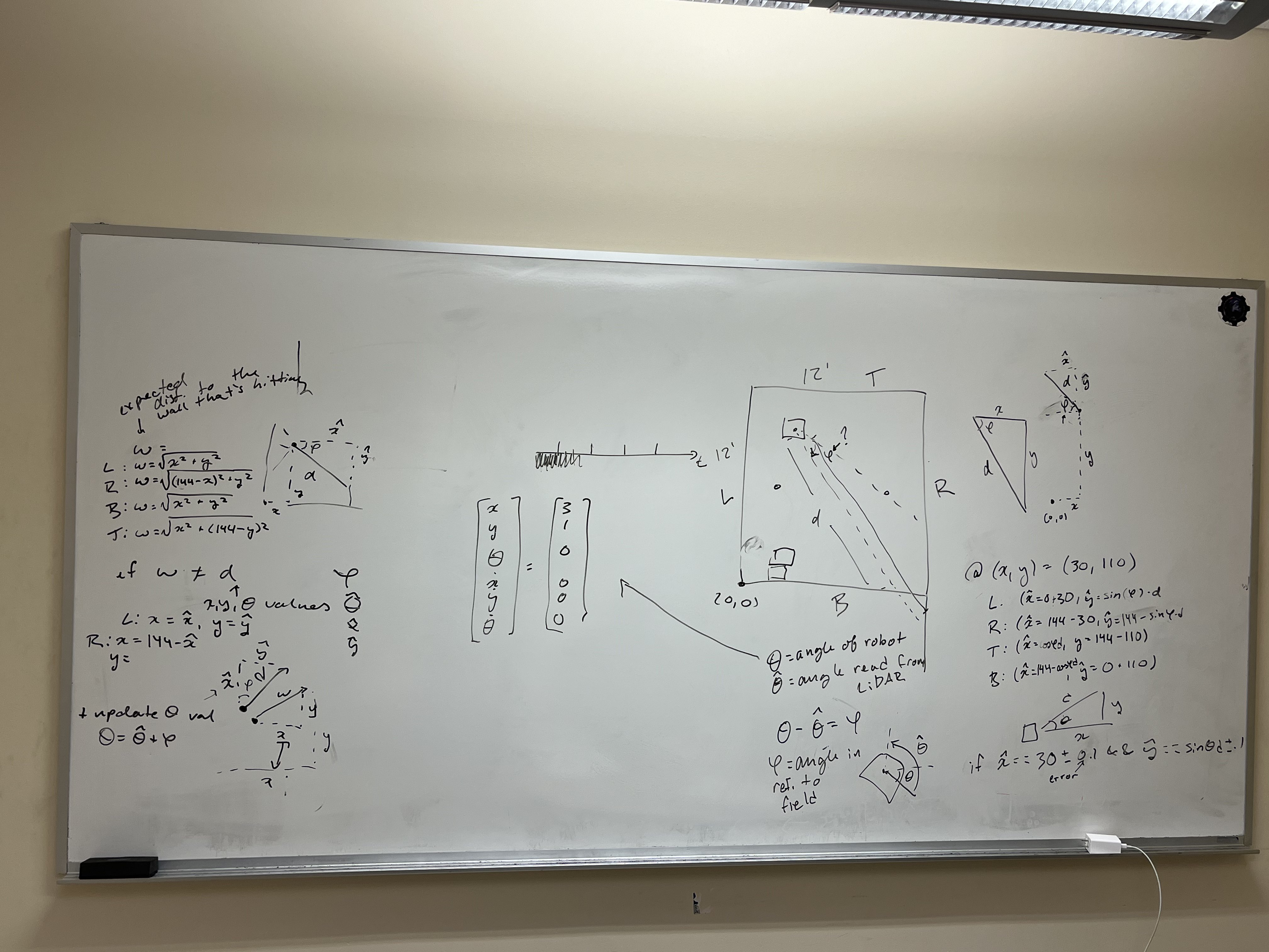
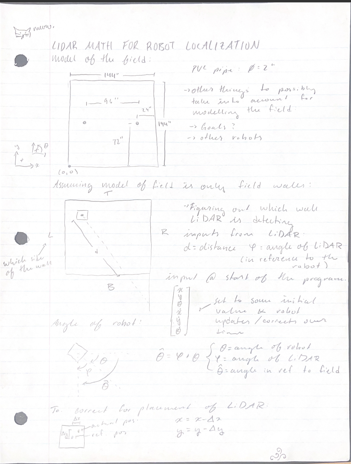
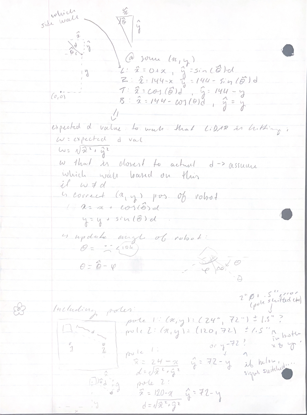
Double-check math
Implement math done above into code
Then, put the code made from math into the UKF
Test said code
Author: Cole Jowett
Participants: Michael Cassidy, Nick Mertin, Avery McFadden, Kieran
Green, Mike Stefan, Laura Cochrane, Cole Jowett
One benefit of the unscented kalman Filter is the ability to increase the accuracy of odometry without any hardware changes by improving the model of the robot. We have seen that the basic model
Does not suffice, as the lack of consideration for acceleration means steady state error can easily accumulate in our velocity. We need an accurate model of how the robot moves based on the current state:
and voltage applied to the motors:
Given the fact that this model should be able to characterize the
entire motion of the robot, we will create it and test it by writing a
full robot simulation in Python. For the purpose of allowing the
simulation to properly transfer into the Kalman filter, we cannot
directly mutate any variables in the state - generally we will only be
applying acceleration, which is then added to
Given that we know all other values in this equation we can solve for
We apply this model to both sides of the drivetrain to obtain
Given the tangential acceleration of our wheels, we can find the
tangential acceleration of the robot by taking their average. The
angular acceleration will be their difference divided by the wheelbase
“
We can now convert
Running the simulation now will show that the robot will drive forwards and backwards properly given an input voltage, but it does not turn properly. The robot slides around as though it is on ice while turning. To fix this assue we need to account for the friction provides a centripetal force to the robot.
The friction that provides a centripetal force will be directly perpendicular to the direction of the robot, and opposing the robot’s direction of sliding. We can estimate the friction by assuming a coefficient of friction of one:
This means that all we have to do is apply an acceleration with the
magnitude
Note that the unit vector in the direction to our right is
It is simple to turn this robot simulation into a version of the predict function. The main difference is that in the robot simulation we know the exact wheel values. Since the predict step happens before every reading, we cannot take a reading and use it to find the wheel speeds. Instead we must calculate the estimate wheel speeds from our current robot state. This is done using the same math that is found in the update function:
After requesting the applied voltage from the motors, we now have all values needed to implement the model. Since the function will depend on the state, noise, timestep, and voltages, it can be said to be of the form:
Implementing the new predict function into the UKF showed promising
results, with the robot no longer being uncertain of
Author: Laura Cochrane
Participants: Laura Cochrane, Matthew Stevenson, Noel Steves
Author: Ryan Jacobson
Participants:
Over March 7th and 8th, the first iteration of the object recognition AI was tested. It proved to be successful at detecting the tri-balls, goal posts, and climbing poles, though it was having some false positives with some objects such as green chairs. More training data for the next iteration was collected to hopefully fix these false positives.
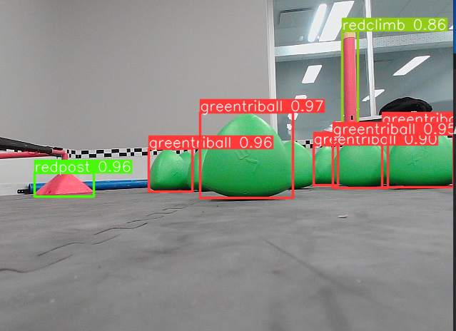
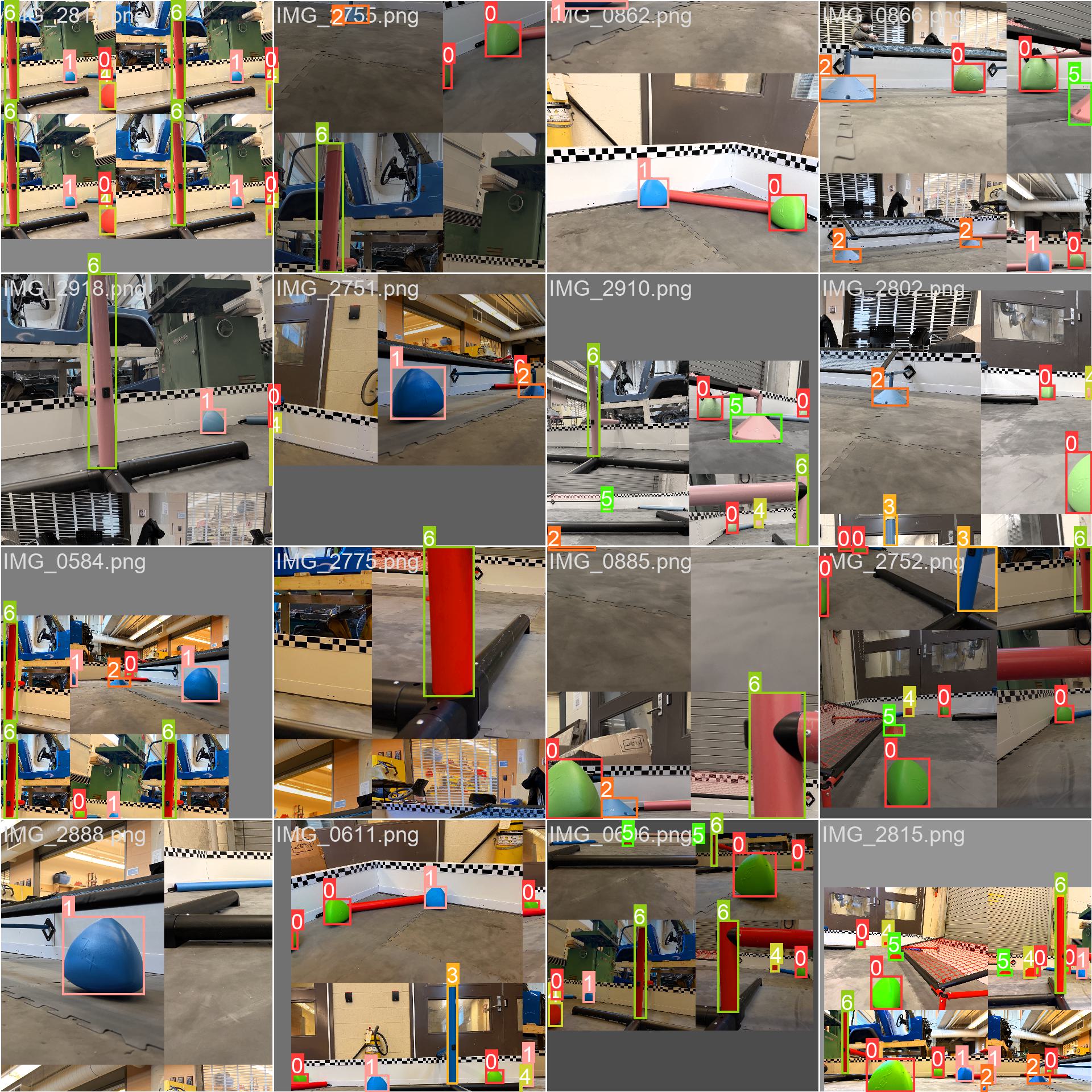
Author: Kieran Green
Participants:
In this meeting we propose various 45s autonomous routes.
Idea 1:
[Auton.jpg](/api/files/61545d9a-7712-46c1-bc61-baa693ca9efc#align=%3Aalignment%2Fblock-center&width=408&height=231 “Here is our first auton. It is broken down into 2 parts. Green is our 15” robot and Yellow is our 24” robot. “)
Green:
Yellow:
Idea 2:
[Auton 2.png](/api/files/3a4761e2-42c4-490e-9b01-d7be1b2bcbbb#align=%3Aalignment%2Fblock-center&width=416&height=214 “Here is our second auton. It is broken down into 2 parts. Green is our 15” robot and Yellow is our 24” robot. “)
Green:
Yellow:
Author: Kashan Rauf
Participants:
The purpose of the meeting was to test some of our subsystem controllers and their respective hardware components to ensure units work as expected
Our testing process is simple, but methodical. We start by testing the unit as a whole to try and find issues or unexpected behavior, if there is an issue our next step is to analyze the code and see if there is an error to be fixed. We then diagnose the exact issue by isolating individual components within the subsystem. An example of this would be when we tested the drivetrain, we saw that the robot would move in uninteded directions, to fix this we looked at the individual motors, then wrote testing code to see which of them were causing issues. After isolating the issue, it is quite simple to fix things by making the necessary adjustments in software, but if this doesn’t work we contact members of our relevant hardware teams to discuss changes to the design or have a component fixed.
Not all of our tested subsystems worked as intended, and not all of them were even tested. The subteam will meet again on Sunday, March 23rd to complete testing after the hardware team’s deadlines pass.
The remaining subsystems to test are below:
This does not include subsystems that can’t be tested (or have ongoing testing completed) on the given date due to having later deadlines, a meeting date to test these mechanisms hasn’t been decided yet.
Author: Mike Stefan
Participants: Nick Mertin, Mike Stefan, Balazs Peterdy, Sebastien
Terrade, Lucas Thomas
The Jetson Nano itself is decently compact but normally comes with a large carrier board. This board is large and inconvenient to mount on the robot. It also does not provide an easy interface with the Smart Ports. This project aims to create a compact carrier board designed to interface with the V5 and our other PCBs. Since it is replacing the off-the-shelf (OTS) carrier board, it must also support all basic functions of the Jetson including power and startup sequencing. The Jetson also has 4 complete CSI busses which greatly simplifies the job of the camera board. The OTS carrier board provides no way to access 2 of these buses. By redesigning the carrier we would also provide access to these buses.
Last year we designed an interface board which sat on top of the OTS carrier board and acted as a power supply and communication manager for the jetson. This board allowed communication with the V5. This board also acted as a passthrough for the camera array.
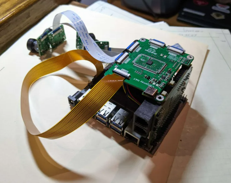
This design had several problems:
Author: Sebastien Terrade
Participants: Nick Mertin, Andromeda Finlayson, Mike Stefan, Laura
Cochrane, Sebastien Terrade, Matthew Stevenson
Design a custom odometry board to accurately calculate the position of the robot from several off-the-shelf sensors. This board will need to interface with 3 AMT102 quadrature encoders, 2 RPLidars and 2 Board mount IMUs. Our robot localization team will take the data from all of these sensors to produce a precise and accurate estimate of our Pose.
We have designed several past iterations of this board, with this one being our 4th version. Last year, our design was limited to just quadrature encoders.
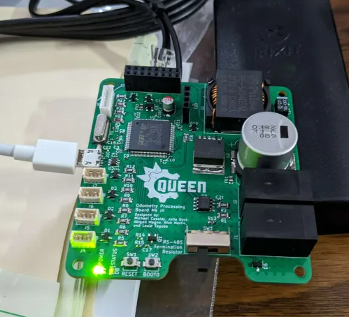
On this board, we used the MCU hardware timers to handle the quadrature accumulation, which ended up having several issues, especially at high data rates. When the robot was moving at full speed, the MCU could not accumulate fast enough, causing our pose estimate to drift over time. The goal of this board is to introduce additional features and fix issues found in previous designs.
Author: Mike Stefan
Participants: Vince Song, Nick Mertin, Mariana Rodrigues de Castro
Siqueira, Mike Stefan, Sebastien Terrade, John Williamson
Based on analysis done by our computer vision team, we determined the ideal camera layout would require 4 independent high FOV cameras. Each of them should be placed on a corner of the robot, facing out to build a full 360-degree view around the robot, with a significant amount of overlap between each camera. The overlap will allow us to develop an effective stereo-vision system for robot localization and to calculate triball positions. This system would look like this:
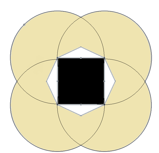
The robot is the center black box, and each camera’s FOV is represented by the shaded circles.
This computer vision system was originally designed by the team last year. The team decided that the 4 camera system was the goal.
To achieve this goal last year we found possible a possible off-the-shelf board that would be able to do what we need to do. As pictured below, we purchased the Arudcam CamArray HAT
After testing we determined that this product does not meet our requirements. It had several issues, namely inconsistent frame rate.
When we requested a new frame we would receive a frame that was taken somewhere randomly between 300ms and 2200ms before our request. Since we wanted to synchronize the camera feed with data from other sensors this was virtually useless. With no accurate way to estimate the age of a frame at runtime, it would be impossible to use the robot localization data in any useless way.
This board was virtually the only off-the-shelf option that appeared to meet our requirements. Since we were unable to find one that meets our requirements, this year we will design our own.
Author: Mike Stefan
Participants: Nick Mertin, Mike Stefan, Balazs Peterdy, Sebastien
Terrade, Lucas Thomas
| 1 | Functional Requirements (top level) |
| 1.1 | Allow communication with the v5 over smartport UART X2 |
| 1.2 | Connect to the 260 pin connector on the Jetson |
| 1.3 | Uninteruptable power supply with secondary battery |
| 1.4 | Allow some kind of breakout for the Camera pins |
| 1.5 | Follow Jetson powerup requirements |
| 1.6 | Fan connector |
| 1.7 | General breakouts |
| 2 | Non-Functional Requirements (top level) |
| 2.1 | Smallest form factor |
| 3 | MicroController |
| 3.1 | UART comms for v5 |
| 3.2 | I2C for comms with battery sensors |
| 3.3 | UART for comms with Jetson |
| 3.4 | UART for comms with camera |
| 3.5 | Breakout capable of controlling the powerup sequence |
| 4 | Camera Board connectors |
| 4.1 | Camera Breakouts for camera 0, 2 , 3, & 4 |
| 4.2 | Camera 0 MCLK and PWDN |
| 4.3 | Provide enough power for cameras + board |
| 4.4 | Breakout CAM I2C |
| 4.5 | Breakout UART x2 |
| 5 | Power |
| 5.1 | Provide 5V at 5A minimum |
| 5.2 | Ripple requirements: 25mV ripple (look at other things connecting to jetson that may be more strict) |
| 5.3 | Follow Jetson powerup requirements: |
| 5.4 | Minimum of 400 ms after VDD_IN is supplied POWER_EN must be set to high |
| 5.5 | Approximately 82 ms after POWER_EN is set to high the SYS_RESET will be set to high by jetson |
| 5.6 | After the SYS_RESET is on the carrier board will automatically recieve power |
| 5.7 | |
| 5.8 | Power off order: |
| 5.9 | SHUTDOWN_REQ* is toggled low by the jetson |
| 5.10 | POWER_EN must be driven low |
| 5.11 | SYS_RESET* will be driven low by jetson |
| 5.12 | At some point SHUTDOWN REQ* will be turned back on after POWER_EN is driven low |
| 5.13 | After SYS_RESET* is driven low, before 1.5 ms must the carrier board be at 3.3 V, and before 4ms must 1.8V be reached. |
Author: Mike Stefan
Participants: Vince Song, Nick Mertin, Mariana Rodrigues de Castro
Siqueira, Mike Stefan, John Williamson
| Description | |
| 1 | Functional Requirements (top level) |
| 1.1 | Support 4, 2-lane MIPI CSI-2 Cameras (15pin) |
| 1.2 | Act as Multiplecer for the CAM I2C bus |
| 1.3 | Timestamp the frames relative to each other |
| 1.4 | Power from jetson board |
| 1.5 | A comms bus with the jetson to send timestamps |
| 1.6 | level shift the 1.8V CAM0_PWDN signal to 3.3V |
| 2 | Non-Functional Requirements (top level) |
| 2.1 | Connect to the Jetson Nano Carrier with some master cable |
| 3 | Microcontroller |
| 3.1 | 5 I2C busses |
| 3.2 | 1 comms channel to talk to jetson (uart) |
| 3.3 | GPIO to trigger XVS pin on 4 cameras at a regular interval |
| 3.4 | 1 UART bus to talk to carrier MCU |
| 4 | Jetson Carrier bus |
| 4.1 | Camera data X4 |
| 4.2 | GND, +3.3v and +1.8V |
| 4.3 | all I2C busses |
| 4.4 | all UART busses |
Author: Sebastien Terrade
Participants: Vince Song, Nick Mertin, Mike Stefan, Balazs Peterdy,
Laura Cochrane, Sebastien Terrade, Lucas Thomas, John Williamson,
Matthew Stevenson
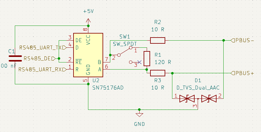
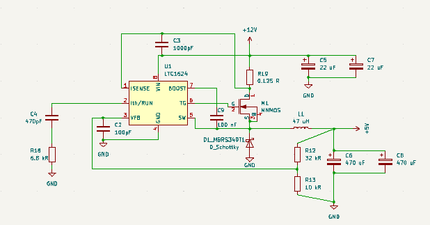
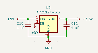
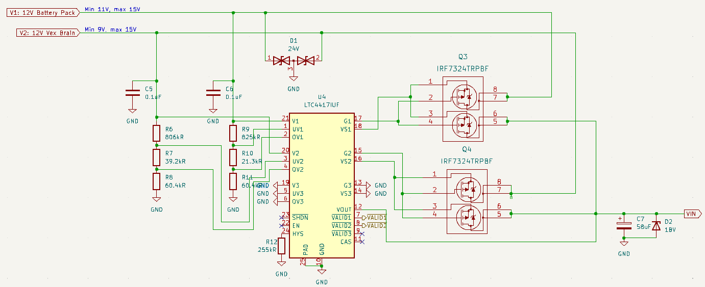
Author: Sebastien Terrade
Participants: Vince Song, Nick Mertin, Andromeda Finlayson, Mariana
Rodrigues de Castro Siqueira, Mike Stefan, Laura Cochrane, Sebastien
Terrade, Lucas Thomas, John Williamson, Matthew Stevenson
| Pin Num | Pin Name | Function | Device | Label | Description/Notes |
| 1 | IOVDD | ||||
| 2 | GPIO0 | UART0 TX | Lidar 1 | Lidar1_UART_TX | UART Communication for Lidar1 |
| 3 | GPIO1 | UART0 RX | Lidar 1 | Lidar1_UART_RX | UART Communication for Lidar1 |
| 4 | GPIO2 | N/A | Gyroscope 1 | Gyro1_INT | Data Interrupt |
| 5 | GPIO3 | PWM1 B | Lidar 1 | Lidar1_PWM | Use PWM channel B for ctrl motor input |
| 6 | GPIO4 | UART1 TX | Lidar 2 | Lidar2_UART_TX | UART Communication for Lidar2 |
| 7 | GPIO5 | UART1 RX | Lidar 2 | Lidar2_UART_RX | UART Communication for Lidar2 |
| 8 | GPIO6 | ||||
| 9 | GPIO7 | PWM3 B | Lidar 2 | Lidar2_PWM | Use PWM channel B for ctrl motor input |
| 10 | IOVDD | ||||
| 11 | GPIO8 | PIO0 | Encoder 1 | A_Channel_1 | Channel A for Encoder 1 |
| 12 | GPIO9 | PIO0 | Encoder 1 | B_Channel_1 | Channel B for Encoder 1 |
| 13 | GPIO10 | PIO0 | Encoder 1 | Index_Channel_1 | Index Channel for Encoder 1 |
| 14 | GPIO11 | PIO0 | Encoder 2 | A_Channel_2 | Channel A for Encoder 2 |
| 15 | GPIO12 | PIO0 | Encoder 2 | B_Channel_2 | Channel B for Encoder 2 |
| 16 | GPIO13 | PIO0 | Encoder 2 | Index_Channel_2 | Index Channel for Encoder 2 |
| 17 | GPIO14 | N/A | Gyroscope 2 | Gyro2_INT | Data Interrupt |
| 18 | GPIO15 | ||||
| 19 | TESTEN | GND | |||
| 20 | XIN | ||||
| 21 | XOUT | ||||
| 22 | IOVDD | ||||
| 23 | DVDD | ||||
| 24 | SWCLK | ||||
| 25 | SWDIO | ||||
| 26 | RUN | ||||
| 27 | GPIO16 | I2C0 SDA | Gyroscope 1 | Gyro1_I2C_SDA | I2C Communication for Gyro 1 |
| 28 | GPIO17 | I2C0 SCL | Gyroscope 1 | Gyro1_I2C_SCL | I2C Communication for Gyro 1 |
| 29 | GPIO18 | PIO0 | Encoder 3 | A_Channel_3 | Channel A for Encoder 3 |
| 30 | GPIO19 | PIO0 | Encoder 3 | B_Channel_3 | Channel B for Encoder 3 |
| 31 | GPIO20 | PIO0 | Encoder 3 | Index_Channel_3 | Index Channel for Encoder 3 |
| 32 | GPIO21 | PIO0 | Encoder 4 | A_Channel_4 | Channel A for Encoder 4 |
| 33 | IOVDD | ||||
| 34 | GPIO22 | PIO0 | Encoder 4 | B_Channel_4 | Channel B for Encoder 4 |
| 35 | GPIO23 | PIO0 | Encoder 4 | Index_Channel_4 | Index Channel for Encoder 4 |
| 36 | GPIO24 | I2C1 SDA | Gyroscope 2 | Gyro2_I2C_SDA | I2C Communication for Gyro 2 |
| 37 | GPIO25 | I2C1 SCL | Gyroscope 2 | Gyro2_I2C_SCL | I2C Communication for Gyro 2 |
| 38 | GPIO26/ADC0 | PIO1 | RS485 | RS485_UART_TX | UART Communication for RS485 |
| 39 | GPIO27/ADC1 | PIO1 | RS485 | RS485_UART_RX | UART Communication for RS485 |
| 40 | GPIO28/ADC2 | N/A | RS485 | RS485_DE | Drive Enable for RS485 |
| 41 | GPIO29/ADC3 | ||||
| 42 | IOVDD | ||||
| 43 | ADC-AVDD | ||||
| 44 | VREG_VIN | ||||
| 45 | VREG_VOUT | ||||
| 46 | USB_DM | ||||
| 47 | USB_DP | ||||
| 48 | USB_VDD | ||||
| 49 | IOVDD | ||||
| 50 | DVDD | ||||
| 51 | QSPI_SD3 | ||||
| 52 | QSPI_SCLK | ||||
| 53 | QSPI_SD2 | ||||
| 54 | QSPI_SD0 | ||||
| 55 | QSPI_SD1 | ||||
| 56 | QSPI_SS_N |
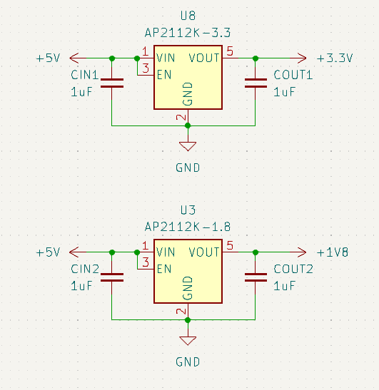
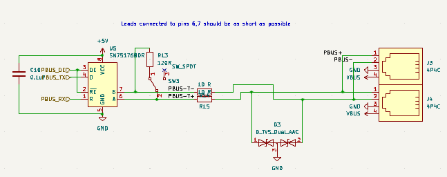
Author: Sebastien Terrade
Participants: Vince Song, Nick Mertin, Balazs Peterdy, Sebastien
Terrade
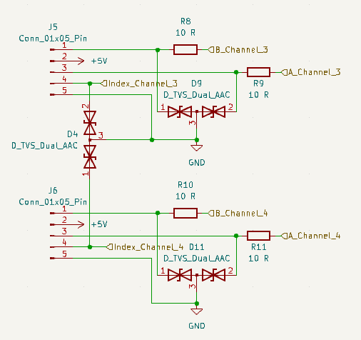
| Pin number | Pin name | Pin function | AF value | Description |
| 1 | PB9 | Breakout | ||
| 2 | PC14-OSC32_IN | LS OSC In | ||
| 3 | PC15-OSC32_OUT | LS OSC Out | ||
| 4 | VDD/VDDA | VDD | 1.7V -3.6V | |
| 5 | VSS/VSSA | VSS | Ground | |
| 6 | PF2-NRST | NRST | reset pin | |
| 7 | PA0 | MCUoff Request | ||
| 8 | PA1 | USART2_RTS_DE_CK | 1 | V5 Comms |
| 9 | PA2 | USART2_TX | 1 | V5 Comms |
| 10 | PA3 | USART2_RX | 1 | V5 Comms |
| 11 | PA4 | MCUon Request | ||
| 12 | PA5 | USART3_TX | 4 | MCU_Jetson UART TX |
| 13 | PA6 | 3 | Breakout | |
| 14 | PA7 | 3 | Breakout | |
| 15 | PB0 | USART3_RX | 4 | MCU_Jetson_USART_RX |
| 16 | PB1 | LED3_R | ||
| 17 | PB2 | LED3_G | ||
| 18 | PA8 | Breakout | ||
| 19 | PA9 | USART1_TX | 1 | CARRIER_UART_TX |
| 20 | PC6 | Breakout | ||
| 21 | PA10 | USART1_RX | 1 | CARRIER_UART_RX |
| 22 | PA11[PA9] | POWER_EN | ||
| 23 | PA12[PA10] | Jetson SYS RESET | ||
| 24 | PA13 | SWDIO | 0 | SWDIO |
| 25 | PA14-BOOT0 | SWCLK | 0 | SWCLK |
| 26 | PA15 | VALID2 | ||
| 27 | PB3 | VALID1 | ||
| 28 | PB4 | LED2_R | ||
| 29 | PB5 | LED2_G | ||
| 30 | PB6 | I2C1_SCL | 6 | bat sensor |
| 31 | PB7 | I2C1_SDA | 6 | bat sensor |
| 32 | PB8 | Breakout |
Author: Sebastien Terrade
Participants: Vince Song, Nick Mertin, Andromeda Finlayson, Mike Stefan,
Laura Cochrane, Sebastien Terrade, John Williamson, Matthew
Stevenson
All teams are finishing up the main schematics and getting ready for design review.
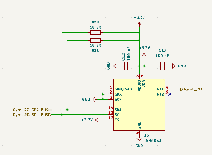
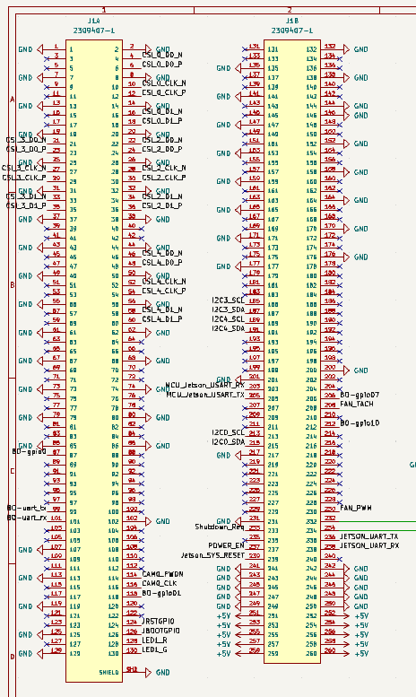
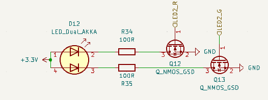
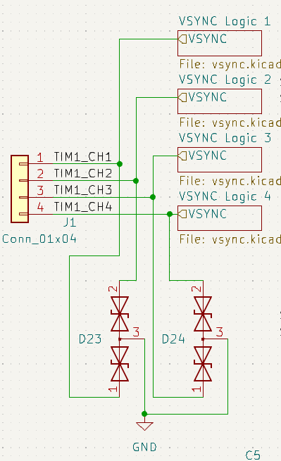
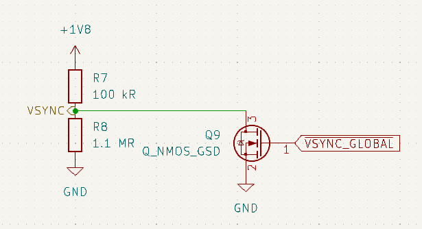

Finish board designs to prepare for design review and find parts for all components.
Author: Nick Mertin
Participants: Nick Mertin, Mike Stefan
Known missing parts: flash memory, USB port, power supply.
Notes:

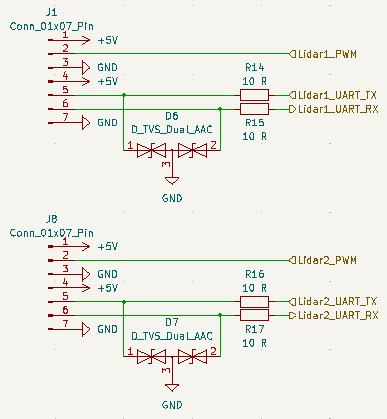
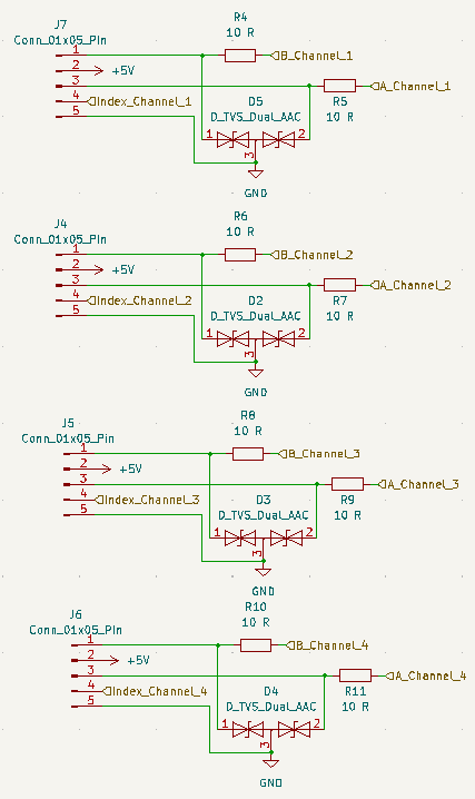
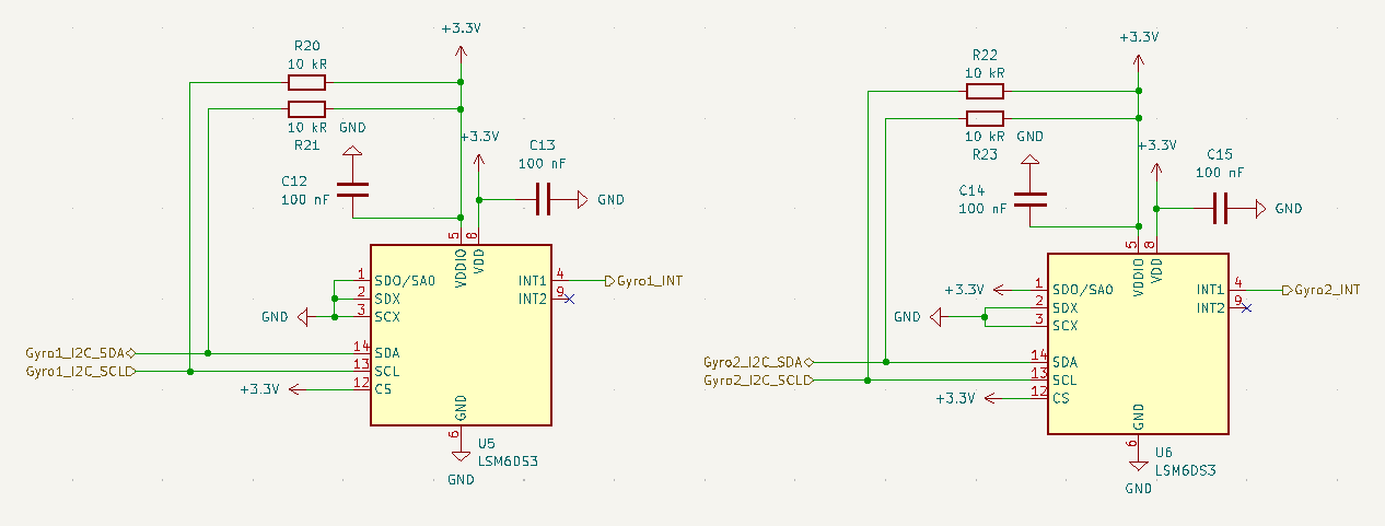
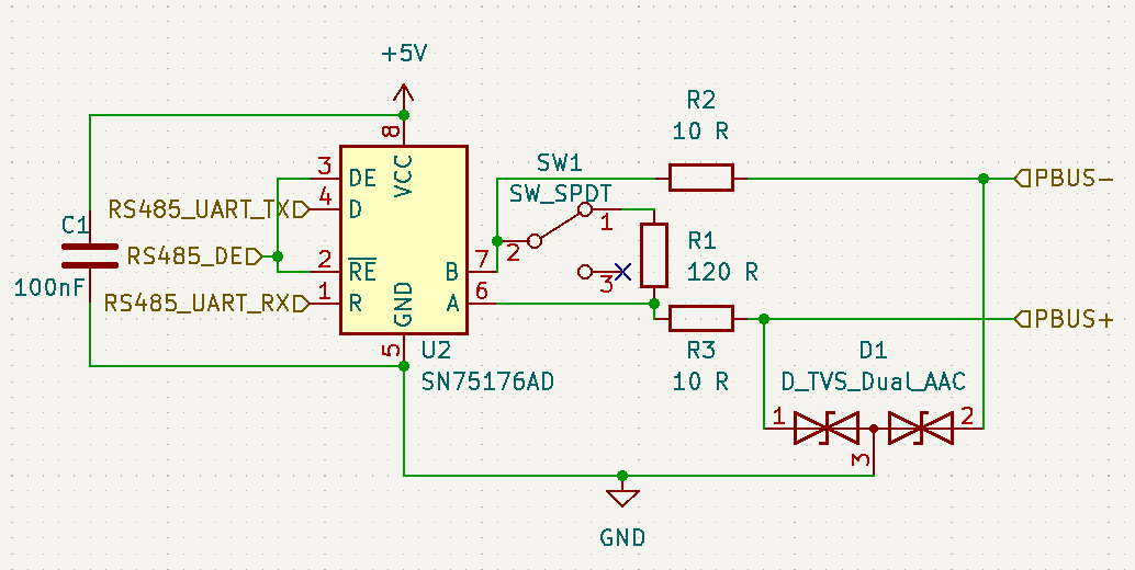
Author: Nick Mertin
Participants: Nick Mertin
The objective was to design the compensator network for the buck converter which will be used on both the Jetson Nano Carrier Board and the Odometry Board Mk IV. The buck converter IC being used is the TPS53313 from Texas Instruments. Its datasheet recommends a compensator network with the following topology:
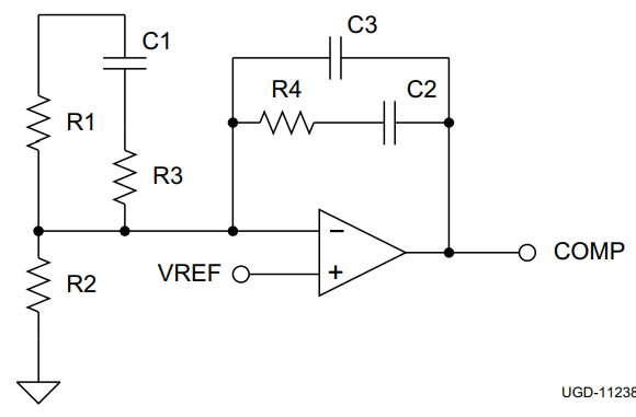
The node at the top of R1 and C1 is connected to the 5V output of the buck converter. The purpose of the compensator network is to counteract the natural frequency response introduced by the inductor, output capacitor, and their equivalent series resistance (ESR) so that the control loop in the buck converter IC can more accurately control the true output voltage and make adjustments in response to changes in load current.
The topology above induces a transfer function with two zeros and three poles, one of which is at DC (0 Hz). The datasheet recommends the compensator network be designed such that zeros approximately cancel out the double-pole of the LC filter at the output, while one pole cancels out the zero created by the output ESR and the other is placed at exactly half the switching frequency to attenuate ripple:
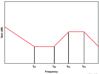
Using the design recommendations in the datasheet, the following component values were chosen:
These create a compensation network which places zeros at 13.3 kHz and 20 kHz, which are the bounds of the range of possible values for the LC filter double pole, and places poles at 133 kHz, the nominal position of the ESR zero, and 500 kHz, half the switching frequency. The bode plot of the compensation network is shown here:
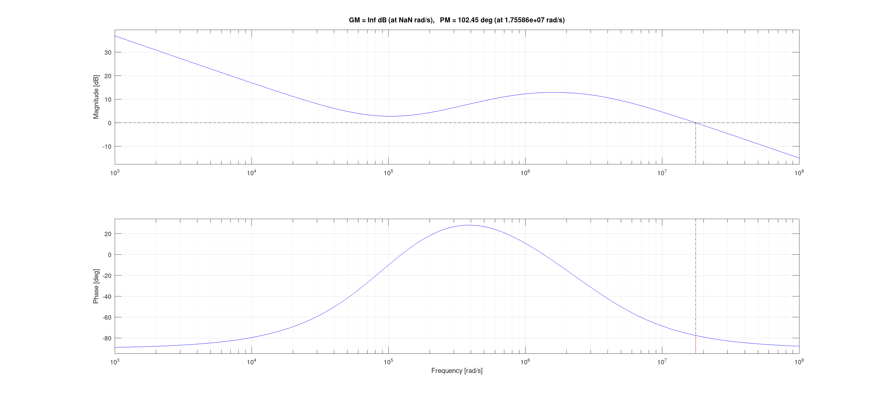
This matches the desired shape as shown above from the datasheet. It also shows the phase margin of 102°, well with in the range for stability (minimum of 45°, per the datasheet).
Author: Mike Stefan
Participants: Nick Mertin, Mike Stefan, Balazs Peterdy
We completed the layout of the jetson carrier board:
Front copper layout:
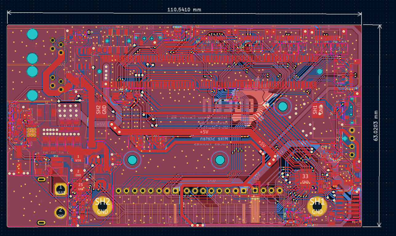
Back copper layout:
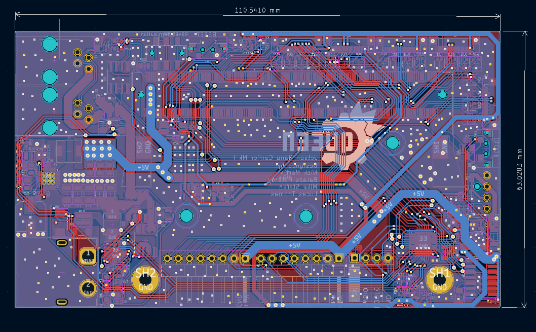
Front render:
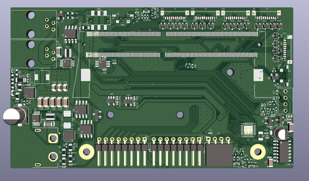
Back render:
Author: Mike Stefan
Participants: Nick Mertin, Mike Stefan
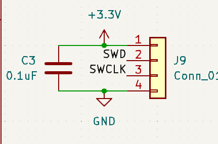
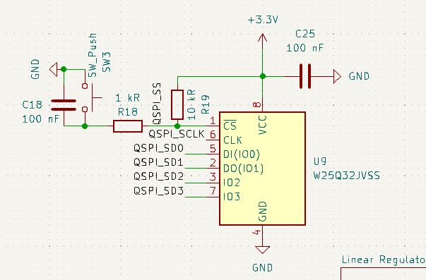
The hardware design document for the RP2040 recommends a 100nf decoupling capacitor for each IOVDD pin, this means that 8 is the recommended amount. The schematic currently includes 4
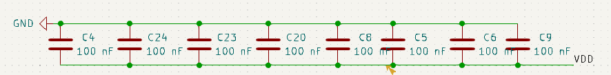
USB was missing 27Ω series termination resistors to bring it to USB impedance specification
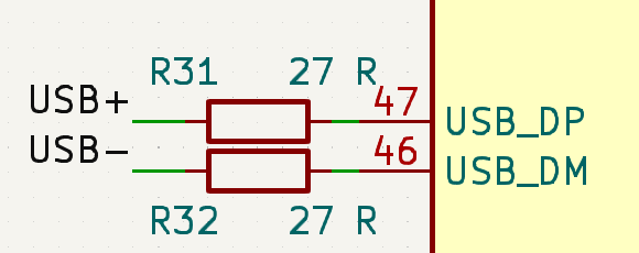
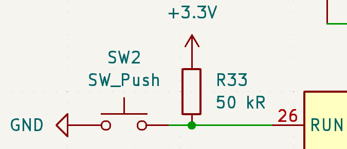
Author: Mike Stefan
Participants: Nick Mertin, Mike Stefan, Sebastien Terrade
We completed the final layout of the odom board:
Front copper layout:
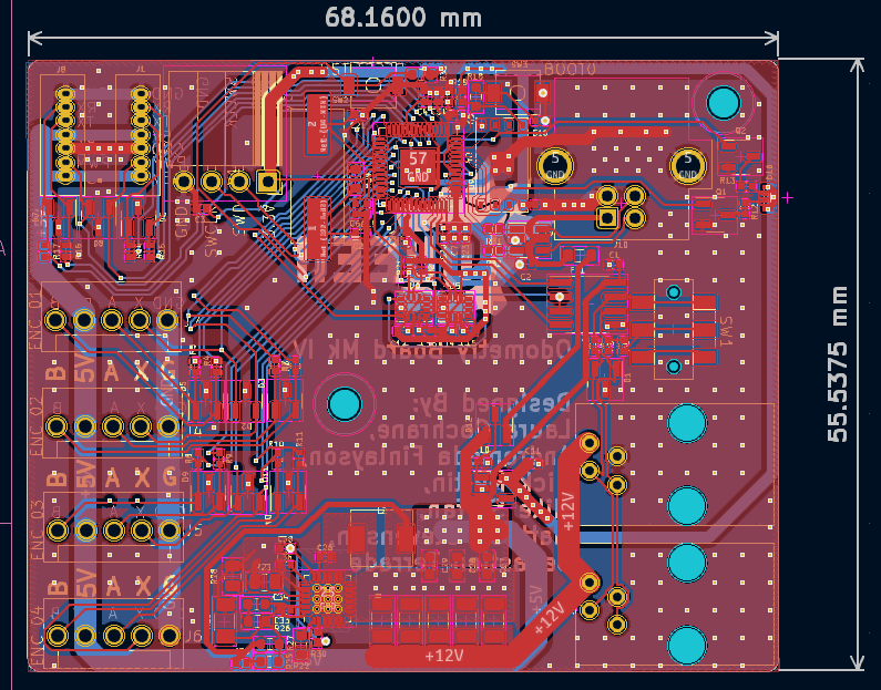
Back Copper layout:
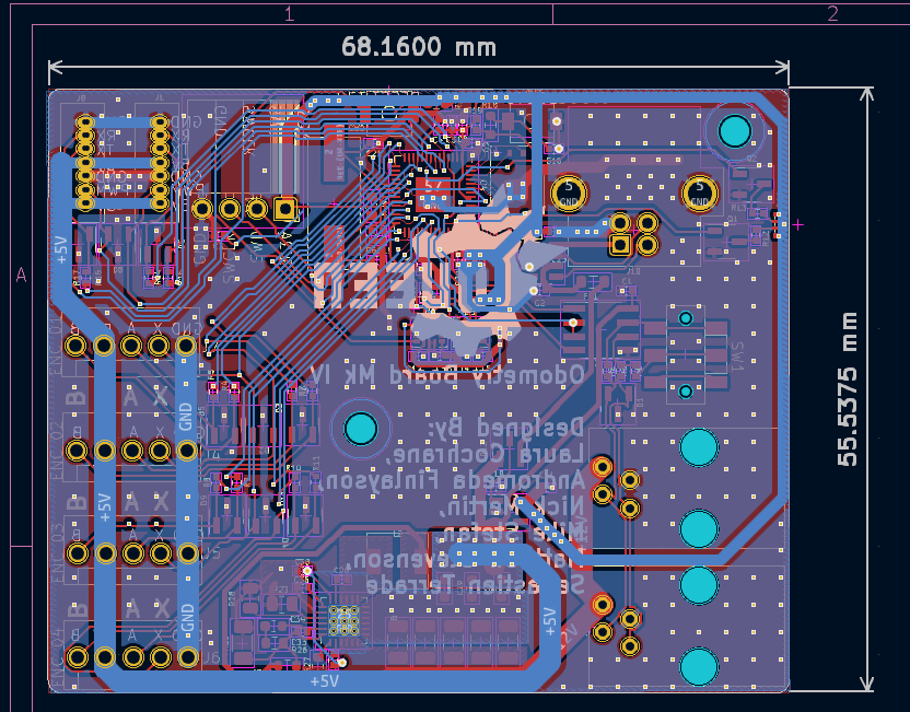
Front render:
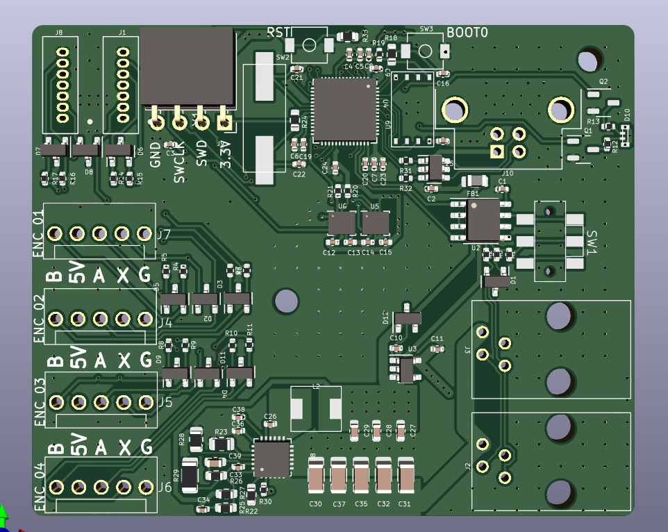
Back render:
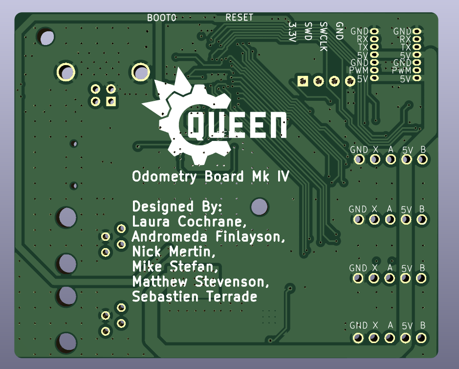
Author: Theo Lemay
Participants: Everyone


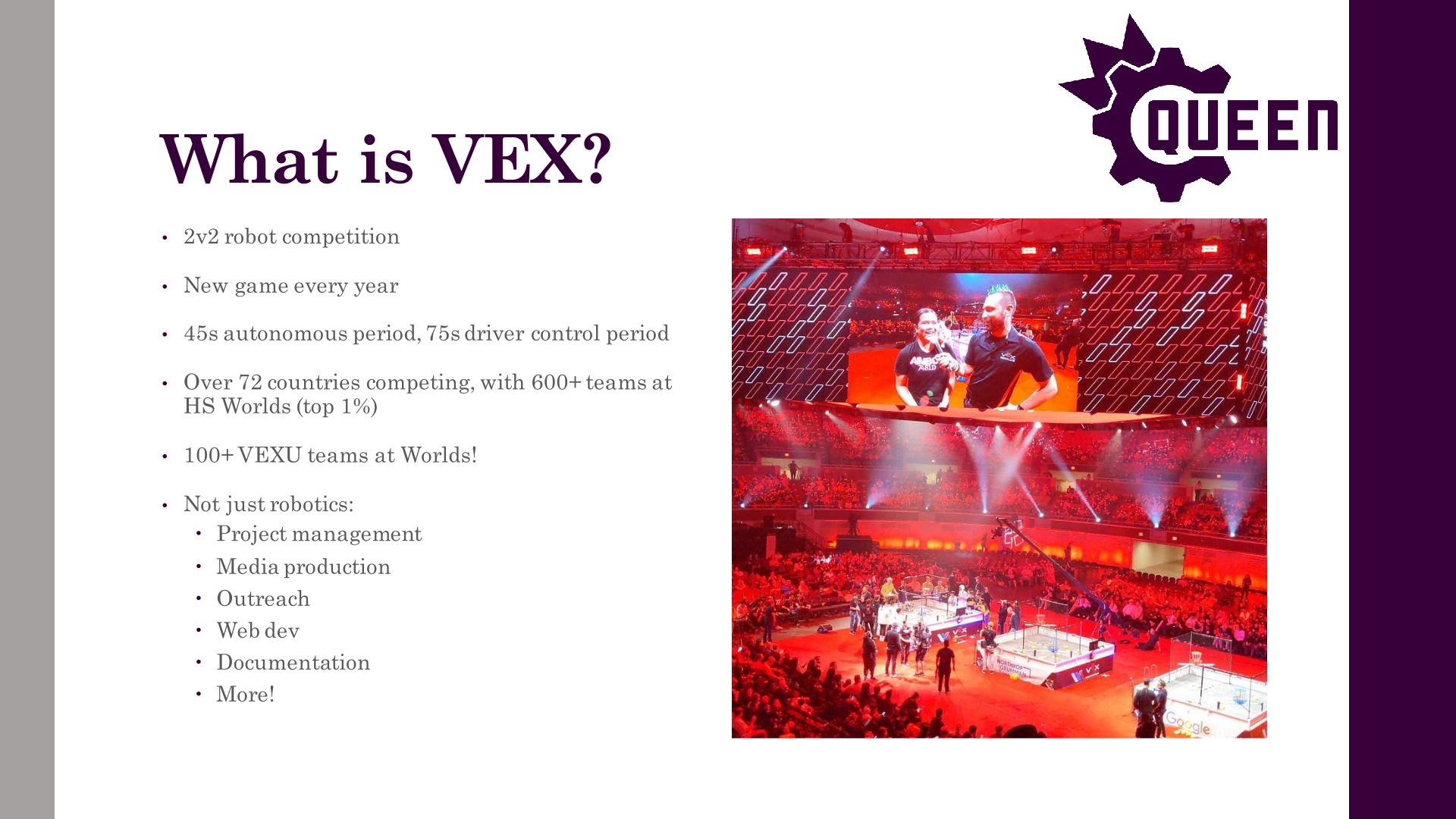
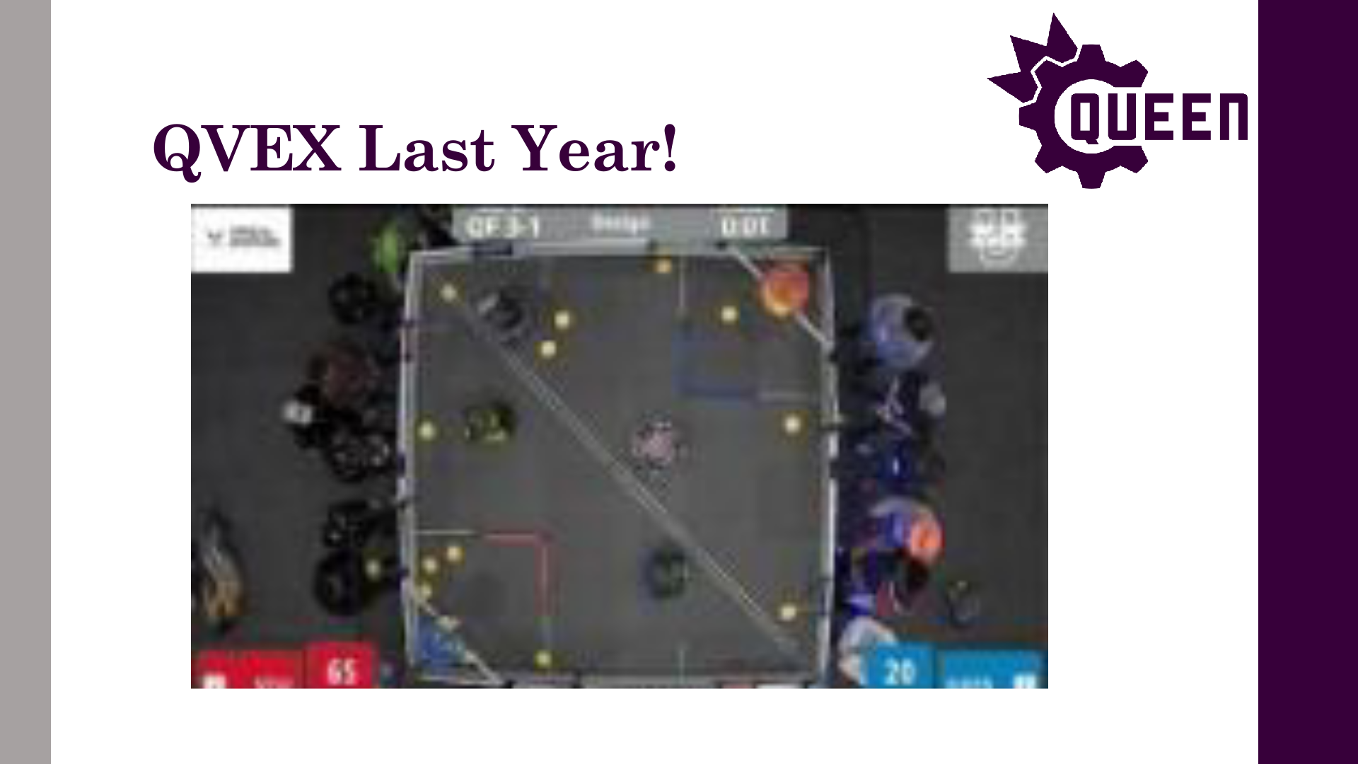

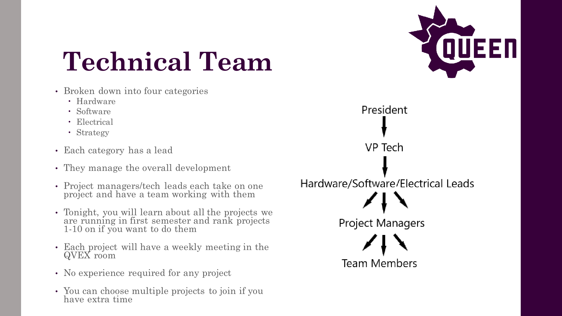
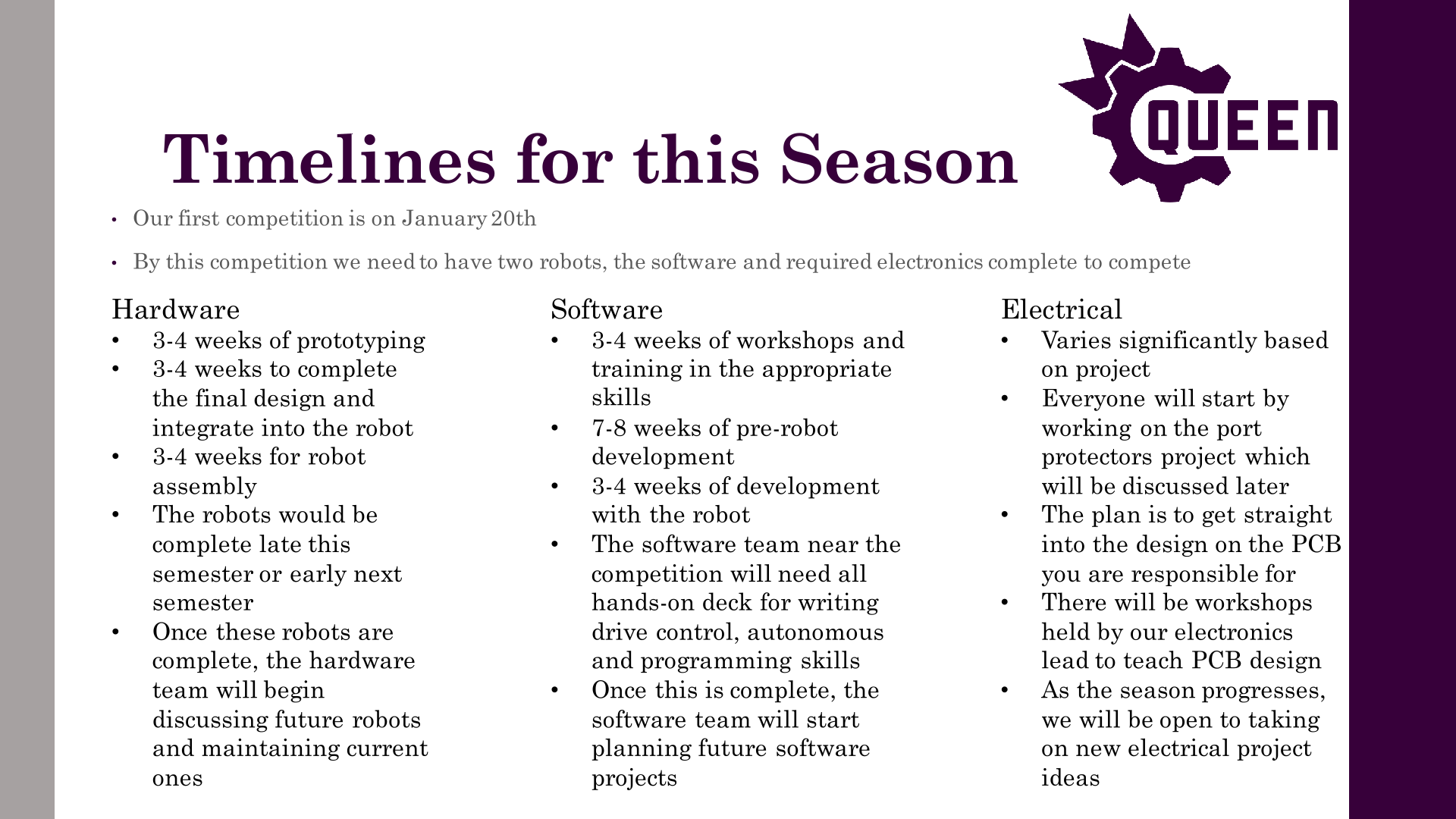


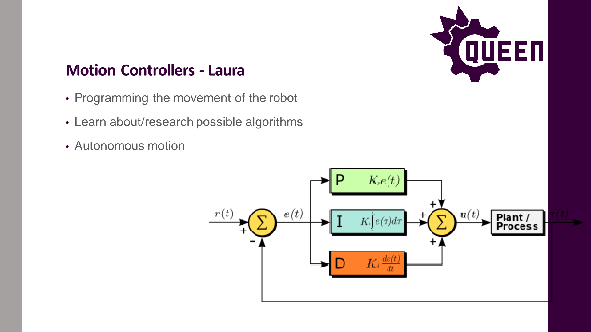
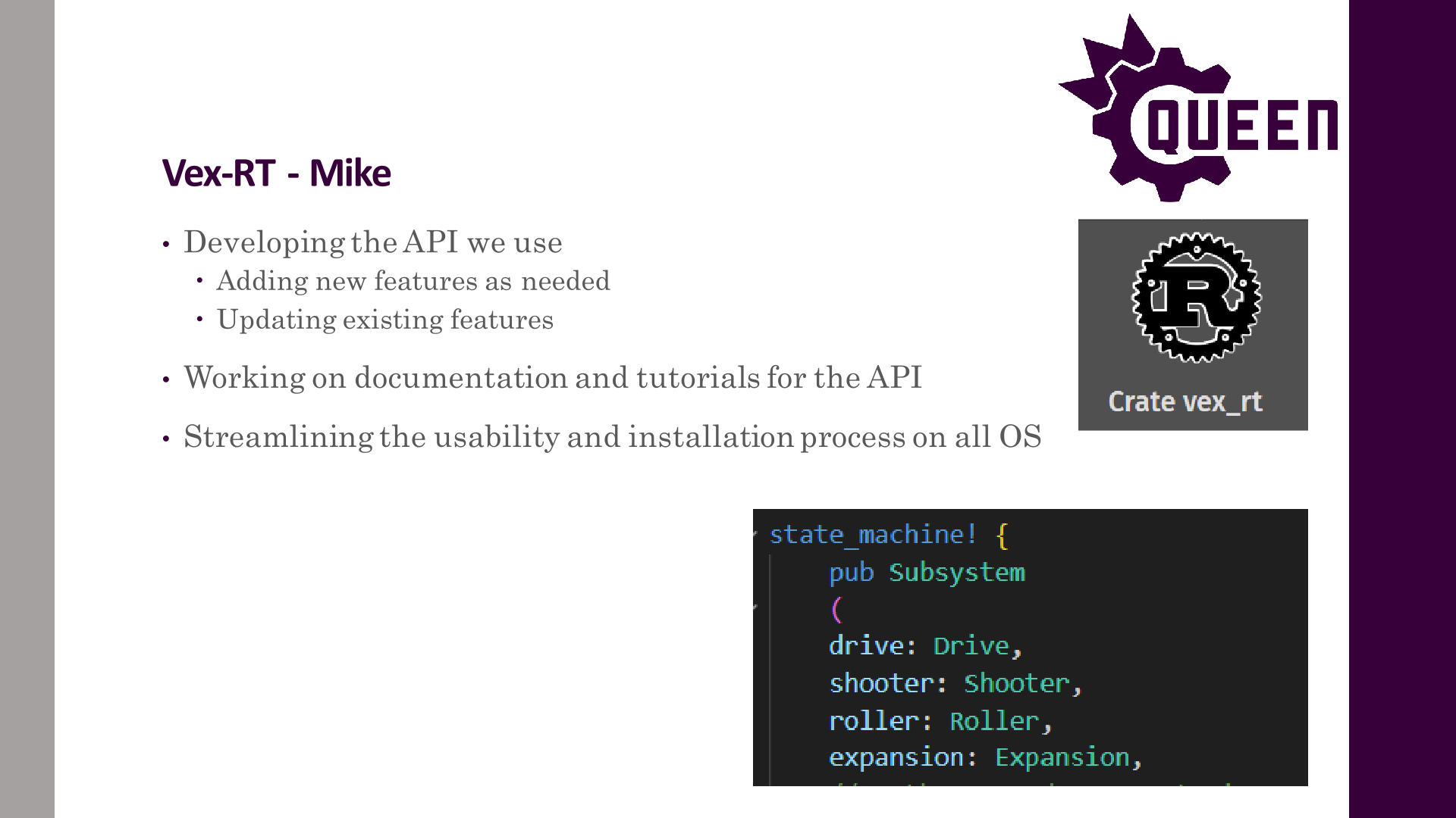
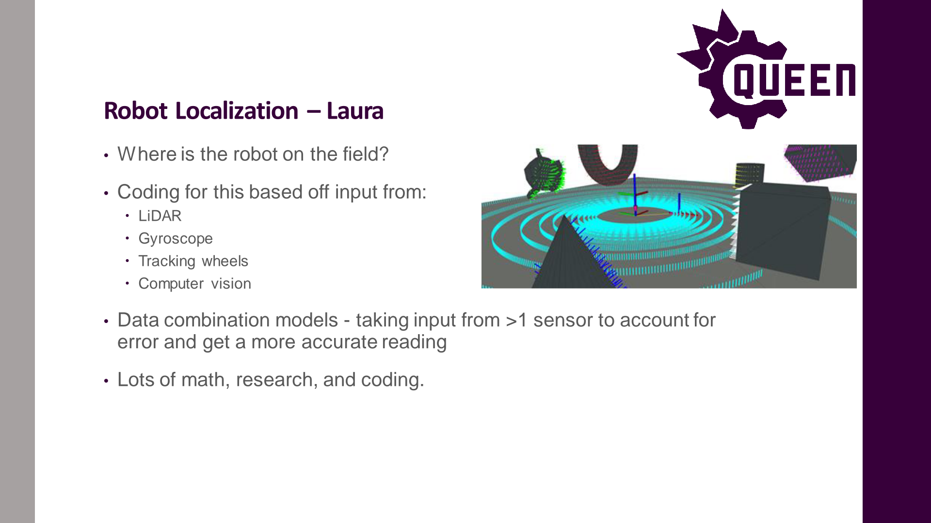
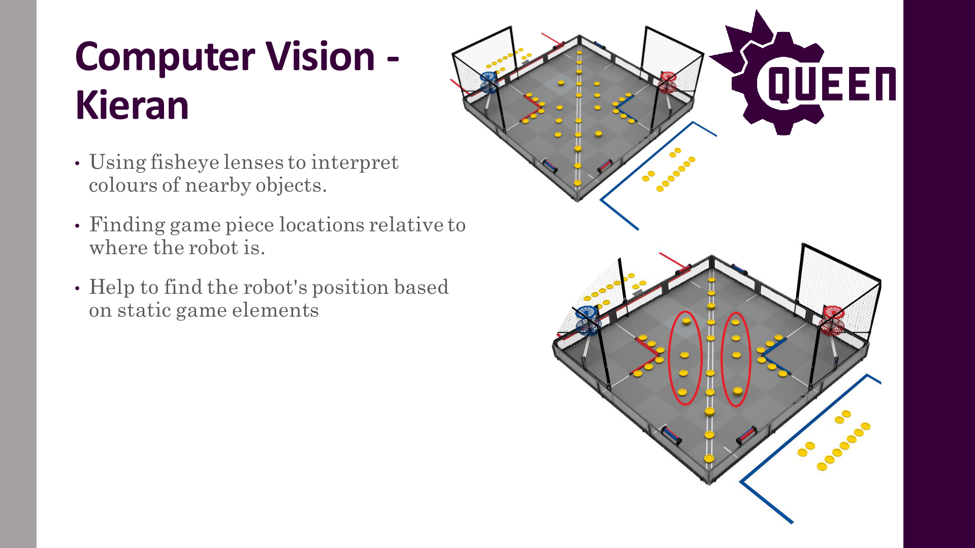
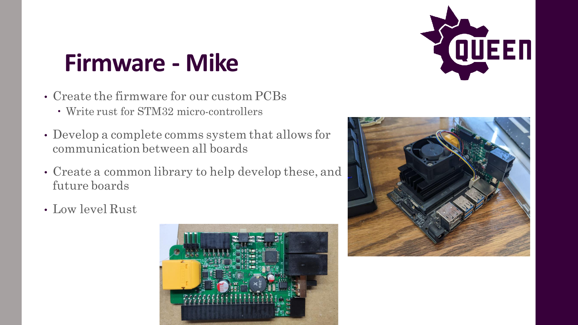
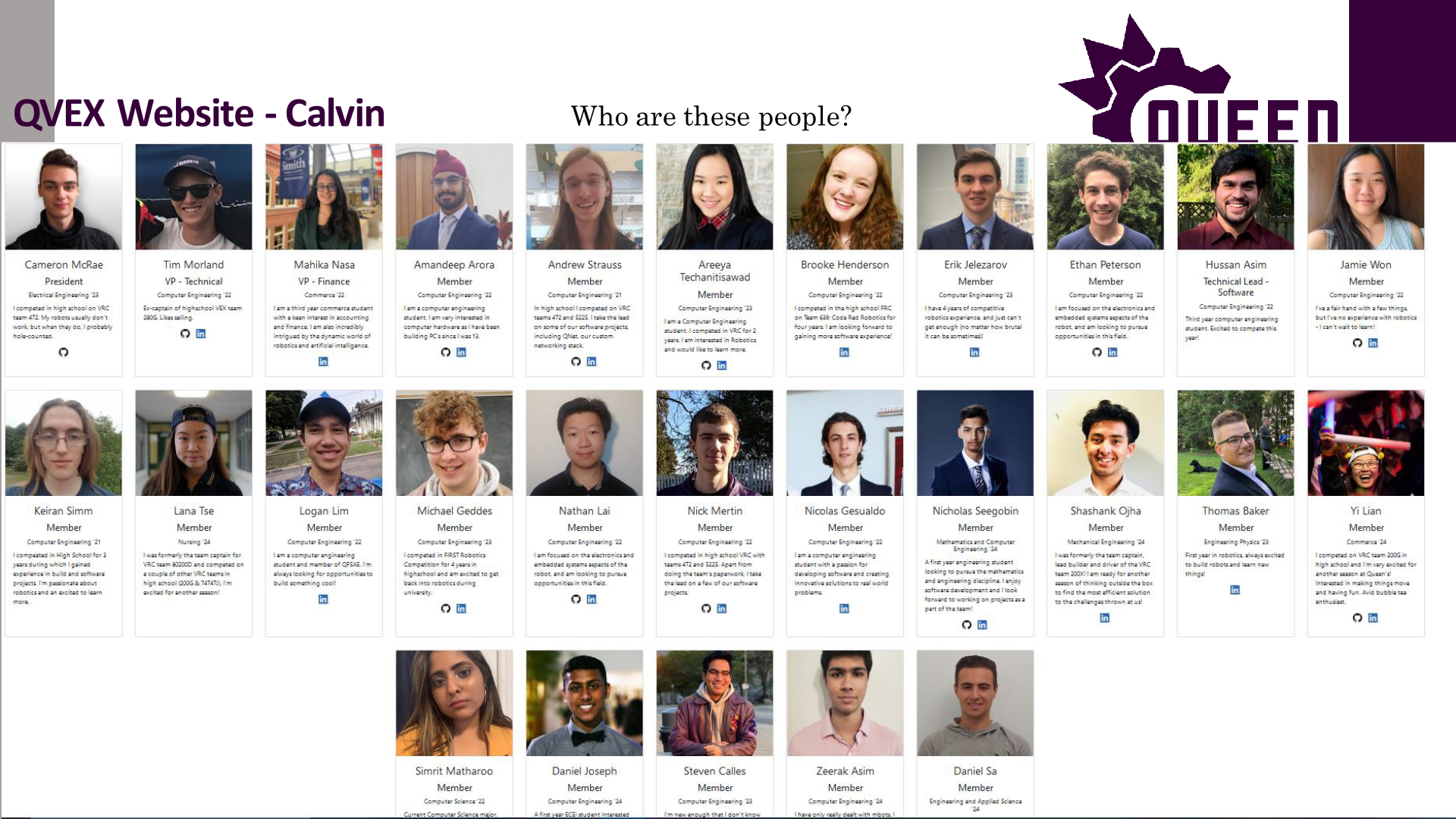
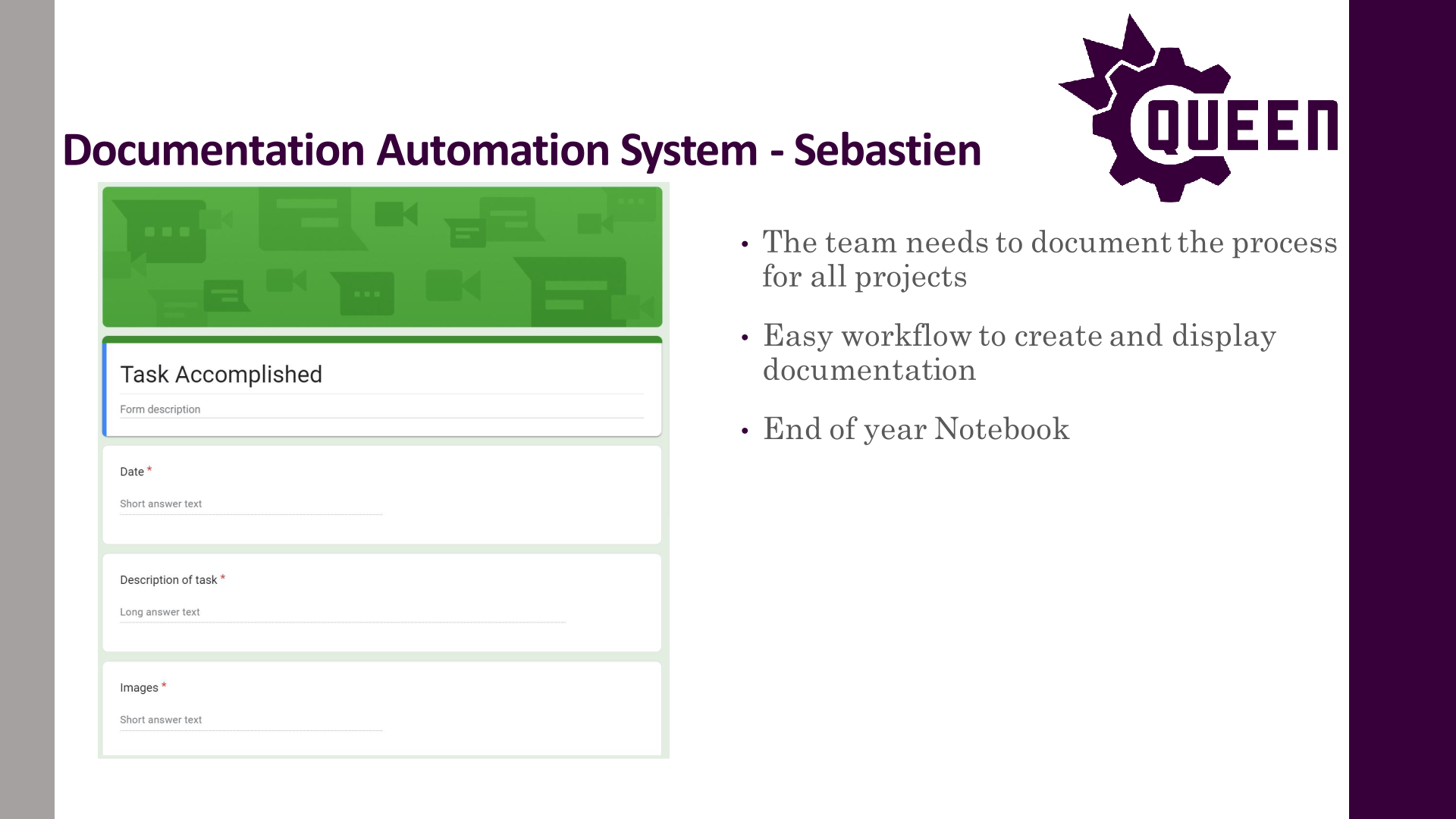
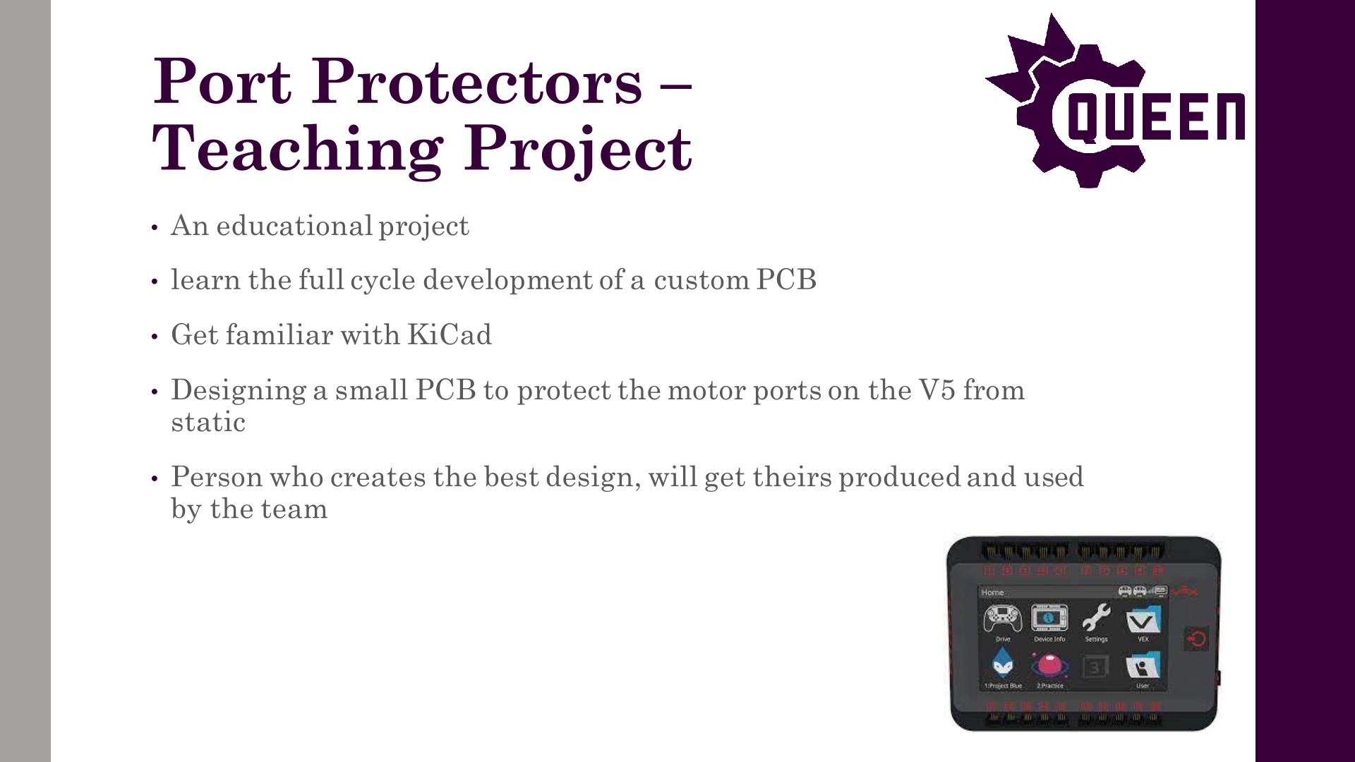
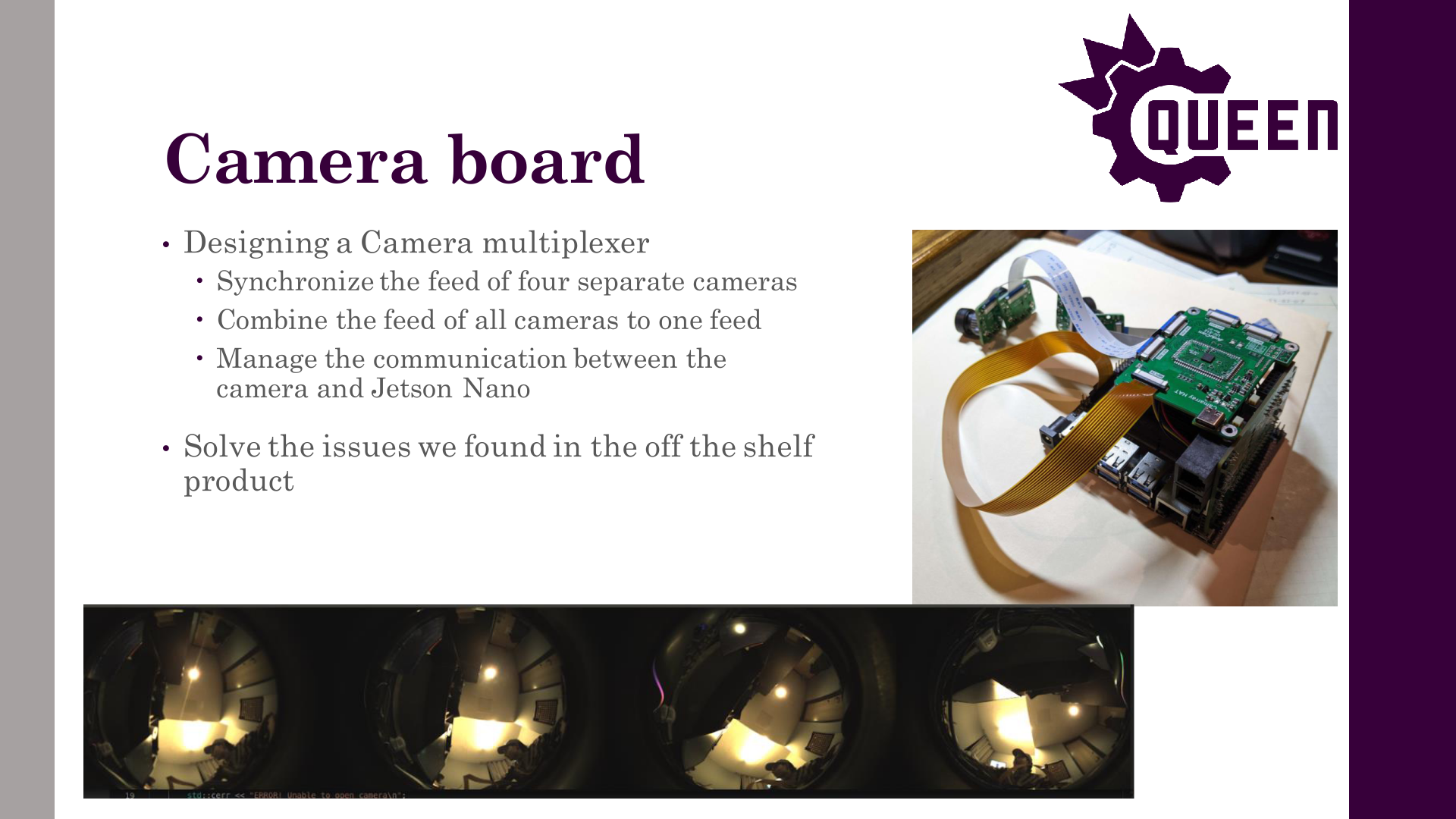
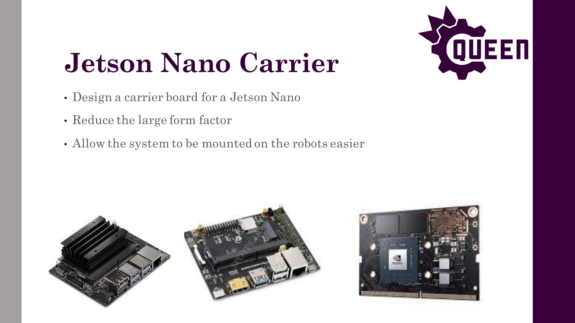
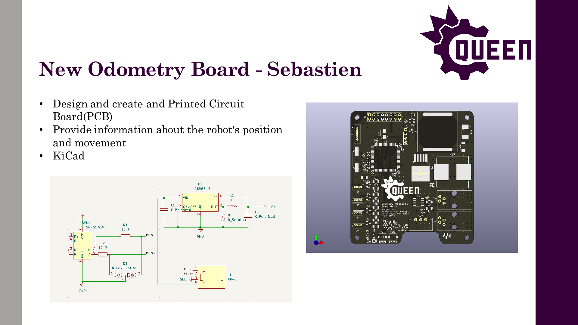
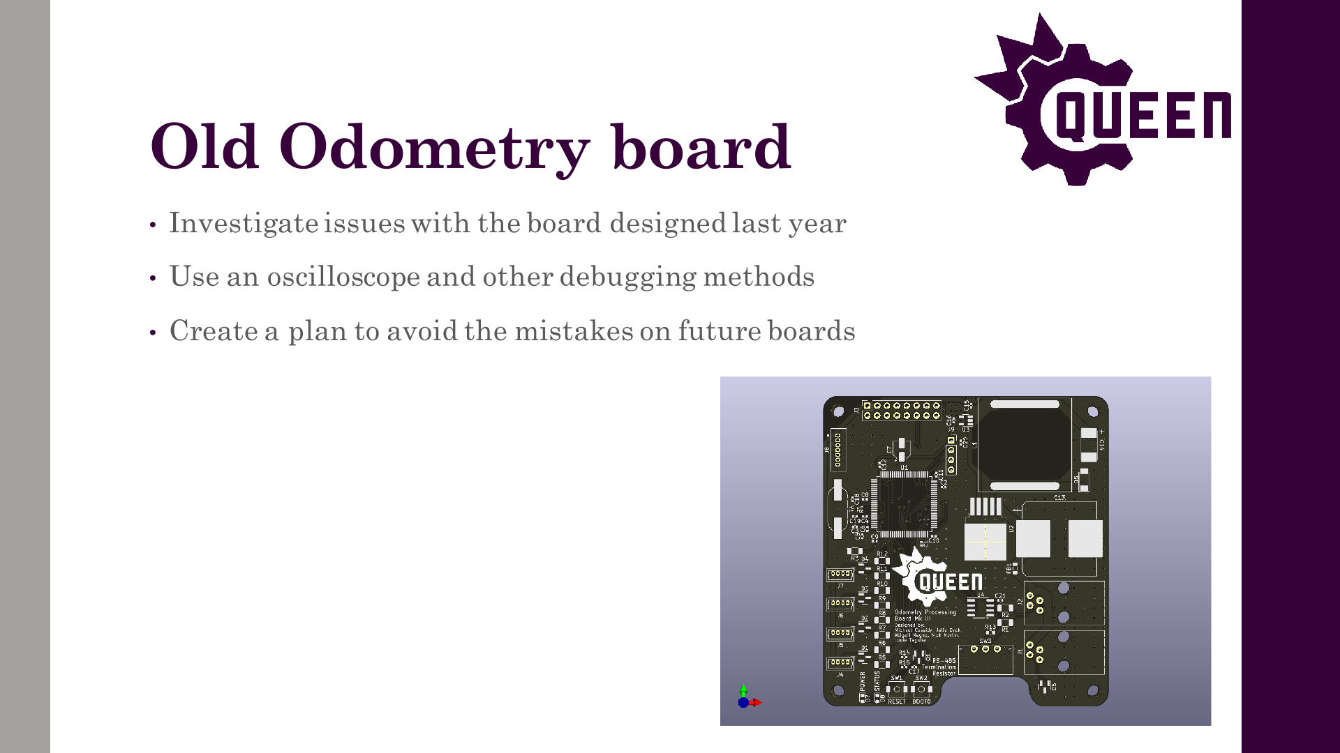
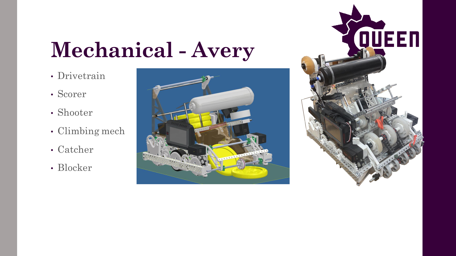
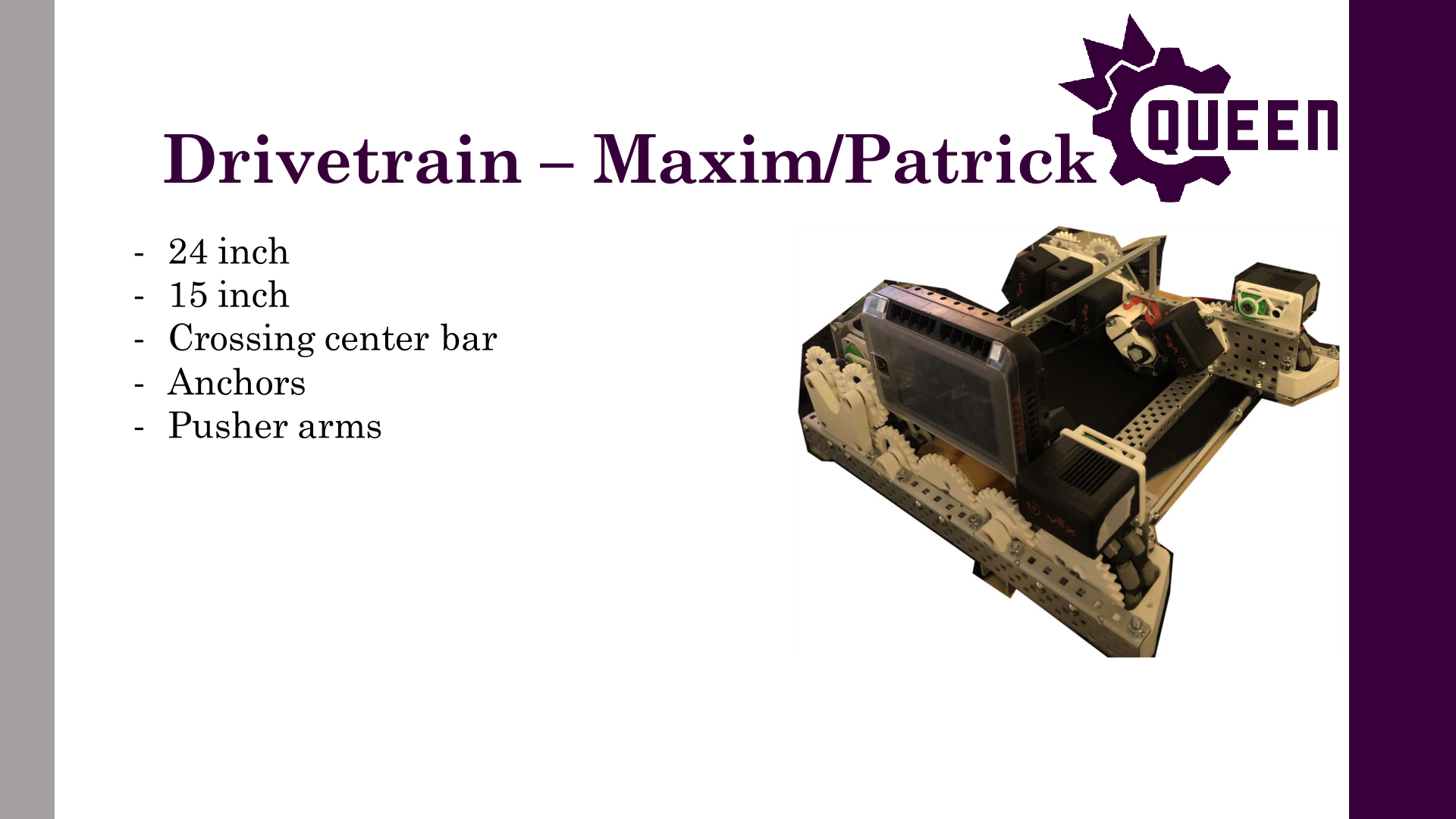
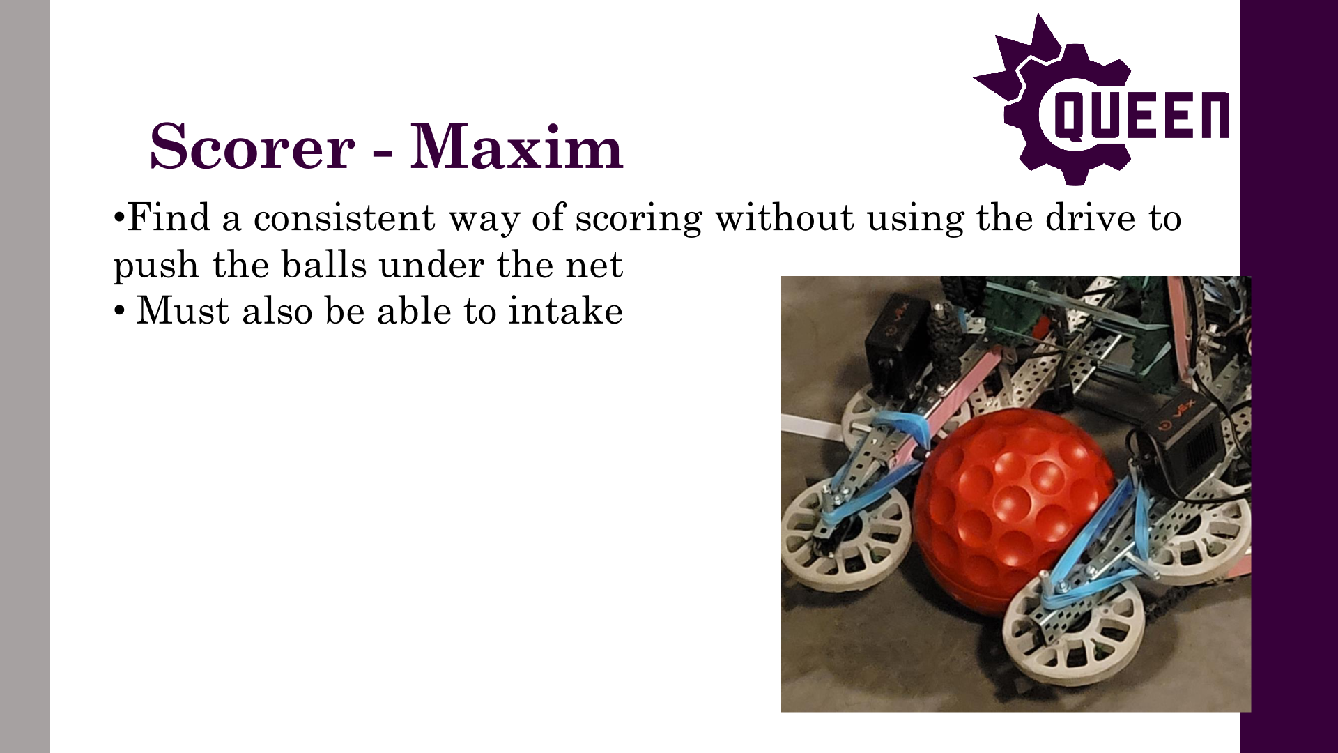
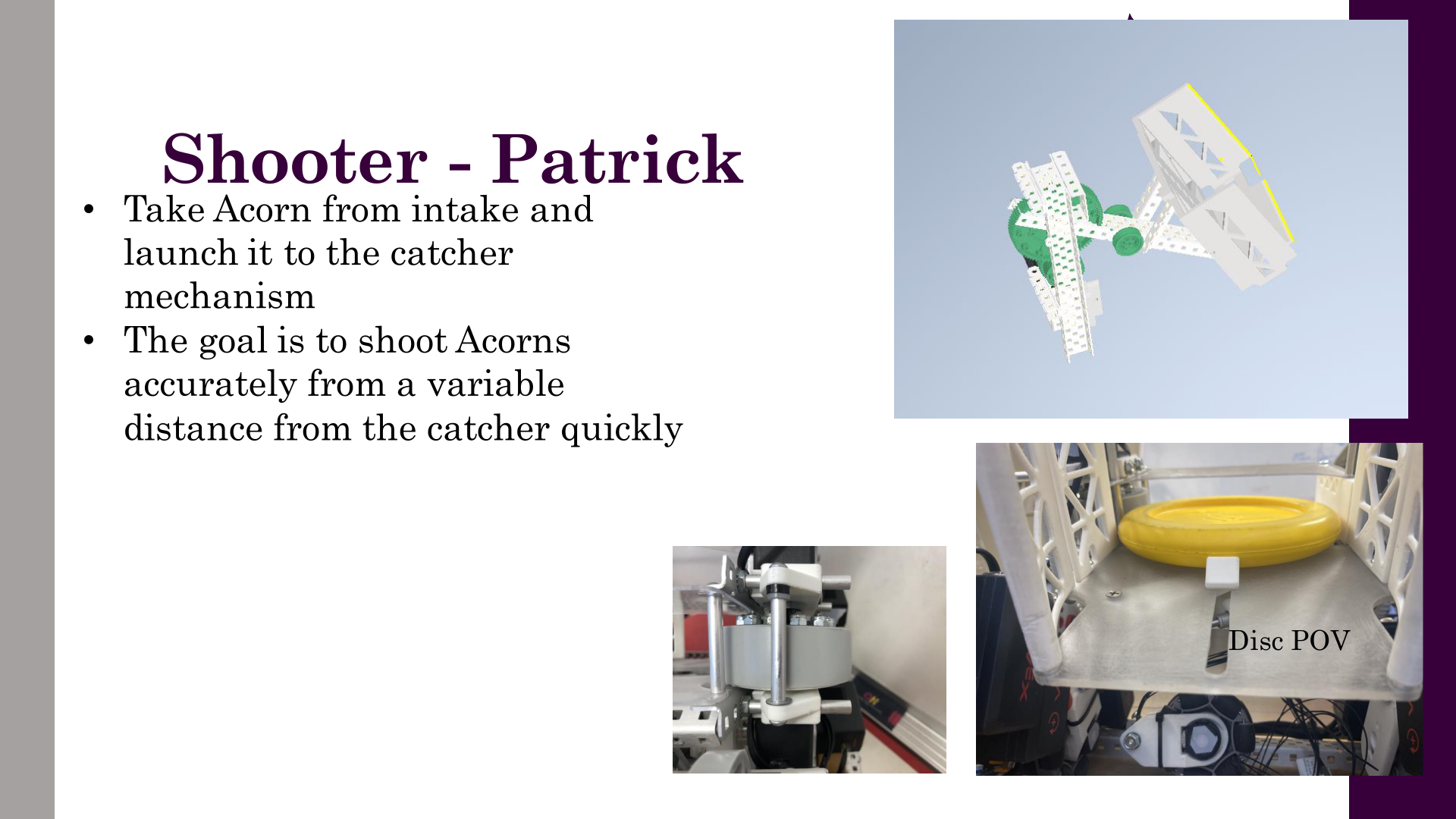
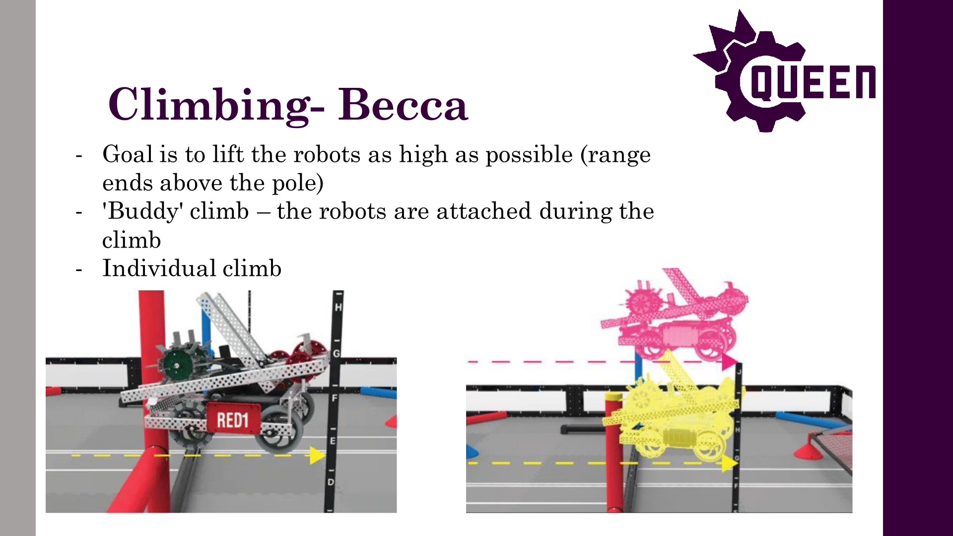

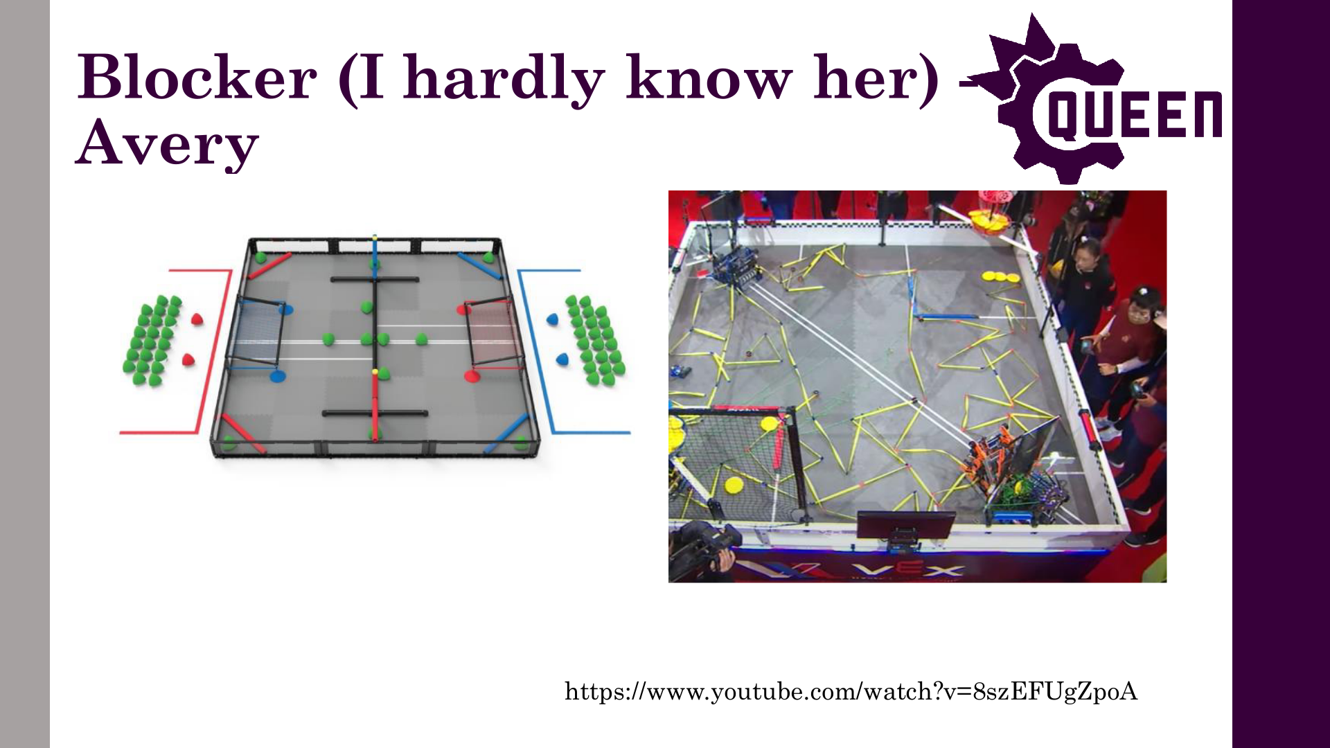
Author: Theo Lemay
Participants: Theo Lemay
September 22, 2023: These last three weeks have been focused on onboarding, hiring, & outreach. An overview of the progress within QVEX as we approach our season kickoff:
October 6, 2023: These last few weeks have been focused on onboarding VPs, planning the general meeting, setting up the technical team, and applying for the dean’s donation.
Author: Theo Lemay
Participants: Michael Cassidy, Theo Lemay
Hey everyone, the exec team has been hard at work planning out the year, and we’ve finalized a timeline for the team! This will help everyone understand what is needed for our first competitions, and what kind of deadlines we are facing.
COMPETITIONS: This year, QVEX will be competing in 3 competitions!
TIMELINE
The focus for our first competition (Jan 20), is ruthlessly simple, effective robots. In early season, most teams are struggling with consistency, especially if they have complex and ambitious designs. We will dominate competition if we consistently score points without the robot falling apart. For that reason, we want to give the software team two weeks to write autonomous programs, and the drive team two weeks to practice driving. With exams and christmas break, that means we need to have robots built and programmed by December 5th. This is a very tight timeline, so we need all tech leads and members to work fast and efficiently to make this happen! (edited)
The timeline until Dec 5 is split up into phases.
Training | Due Nov 6.
In the next 3 weeks, each subsystem (hardware, electrical, software)
will be doing training.
Phase 1 (Complete Functional Prototype) | Due Nov
12.
Each subteam will have 4 weeks to create a functional
prototype of their design. This includes:
This is also when @VEX-RT needs to have completed their refactoring, @Robot Localization needs to have picked hardware and made a plan, @Subsystems needs to have some basic code to power the robots, and all other software teams need to have a functional prototype and plan. Phase 2 (Complete CAD Design) | Due Nov 26. The hardware team needs to have a fully-assembled CAD design by Nov 26, including a model of all electrical components. All the software teams need to have a functional system, ready for robot testing. @Robot Localization needs their math done, @Motion Controllers needs their algorithms designed, @Firmware needs to have everything written, etc.
Phase 3 (Building and Testing) | Due Dec 5. The hardware team will use these two weeks to fully build the robot according to their CAD and give the software team a chance to test algorithms. This is when all subteams need to have everything completed. This is also when @Electrical will have finished the new Odometry board and the Jetson Nano Carrier board, so that @Firmware can test their code in the new year. Phase 4 (Competition Prep) | Due Jan 19. This is mostly the software team’s time to shine. @Motion Controllers and @Subsystems will have from Jan 8-11 to tune, and then the software team needs to write autonomous programs. The drive team, led by @Charles Lapointe | Senior Strat , will also need to practice before the competition.
This will be a crazy couple months, but if all goes to plan, we will definitely win Nationals! Looking forward to seeing what the team can do.
Author: Michael Cassidy
Participants: Everyone
Scorer Team
Shooter Team
Catcher Team
Scouting Team
Blocker Team
Other Notes
Electrical Team
Vex-rt Team
Firmware Team
Documentation System Project
Hardware Workshops
Climbing Team
Motion Controllers Team
Computer Vision Team
State Machines Team
Website Team
Author: Theo Lemay
Participants: Everyone


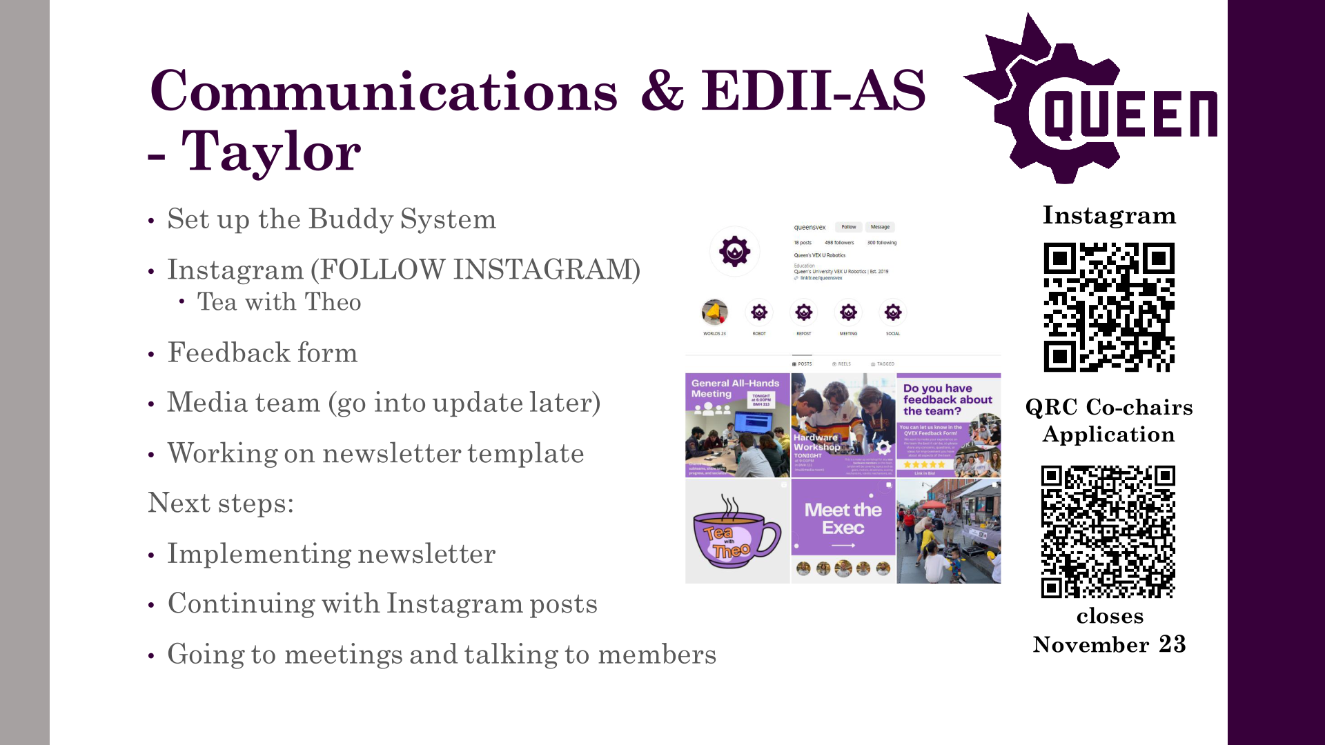


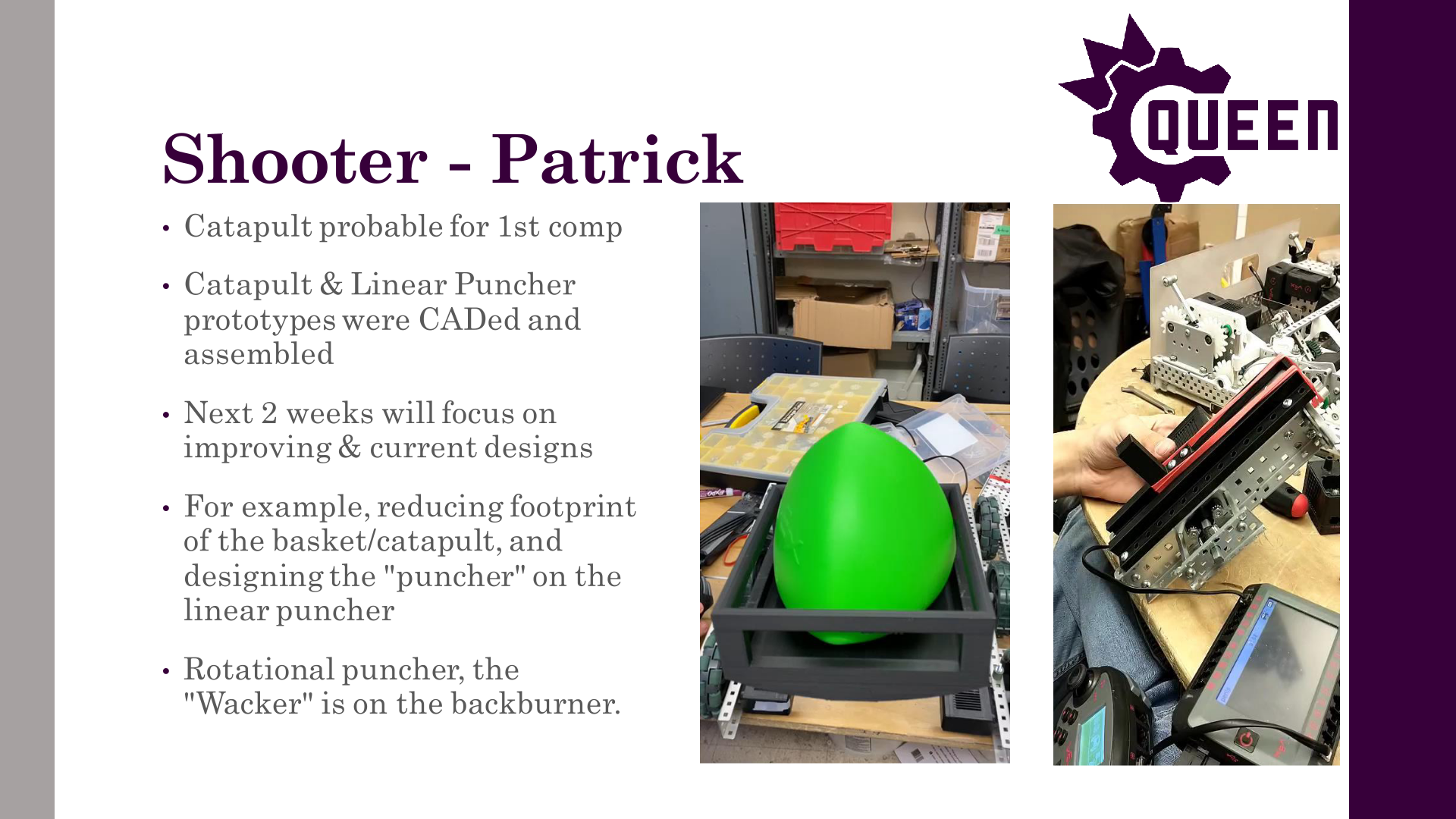
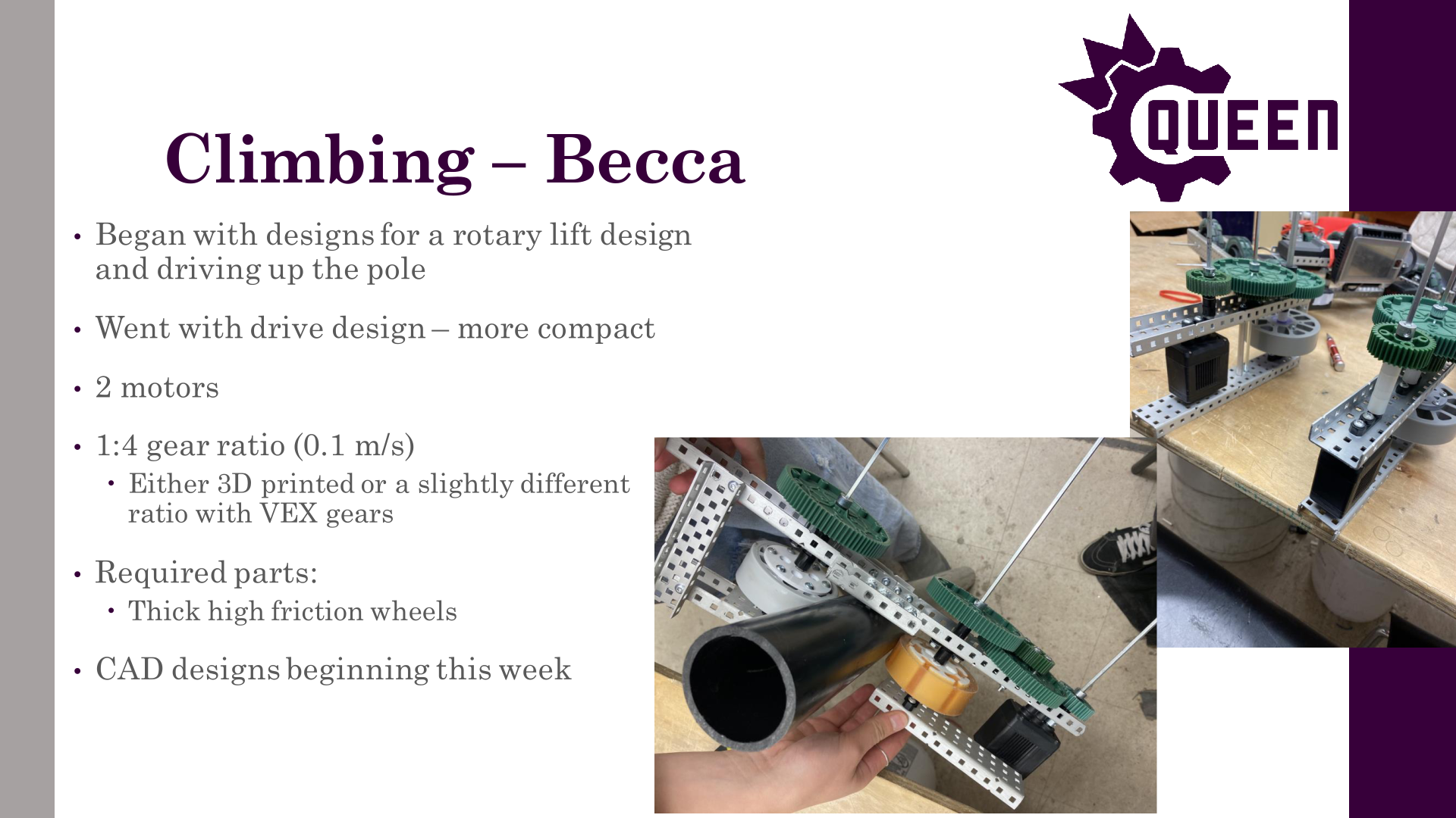
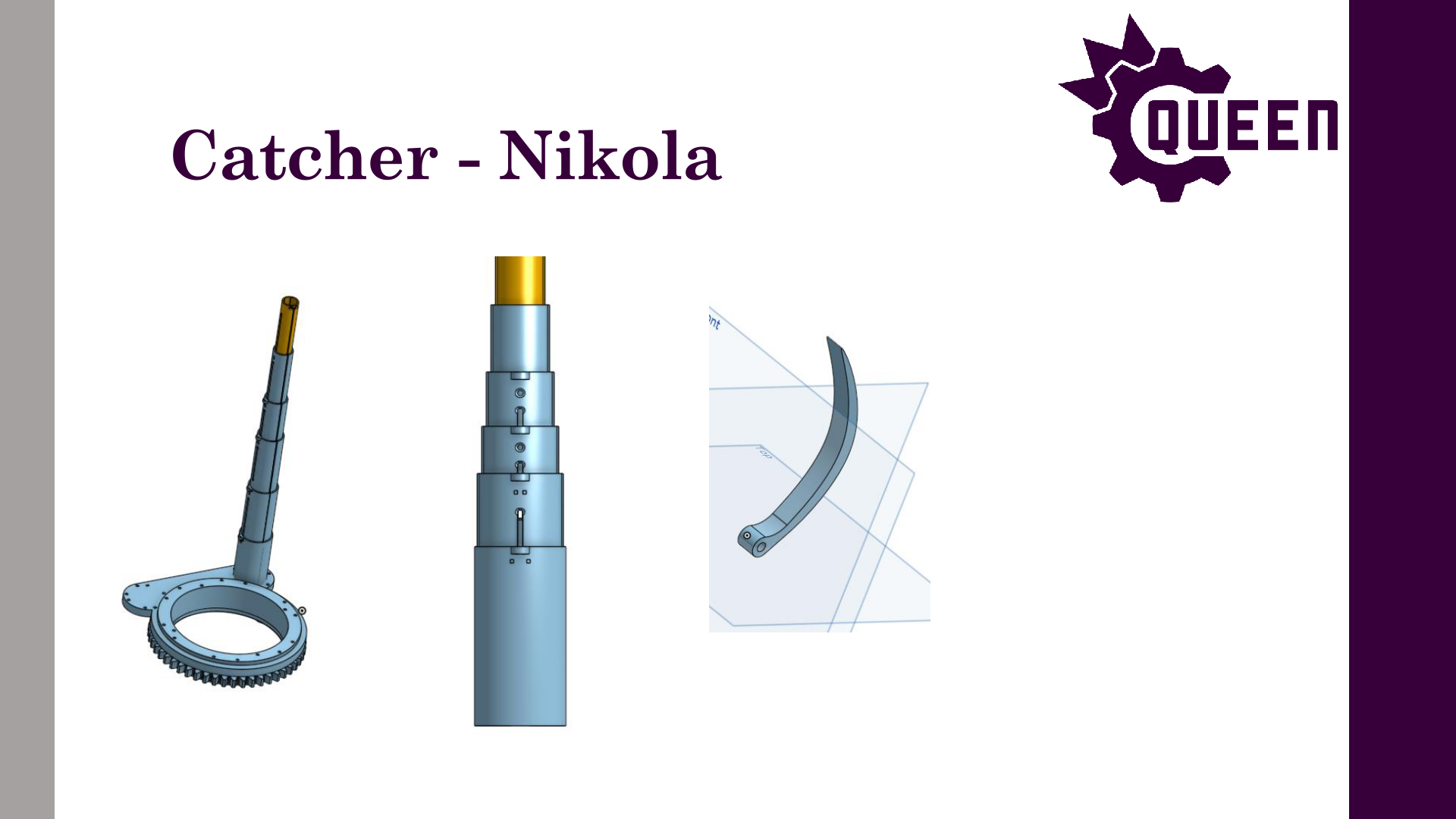
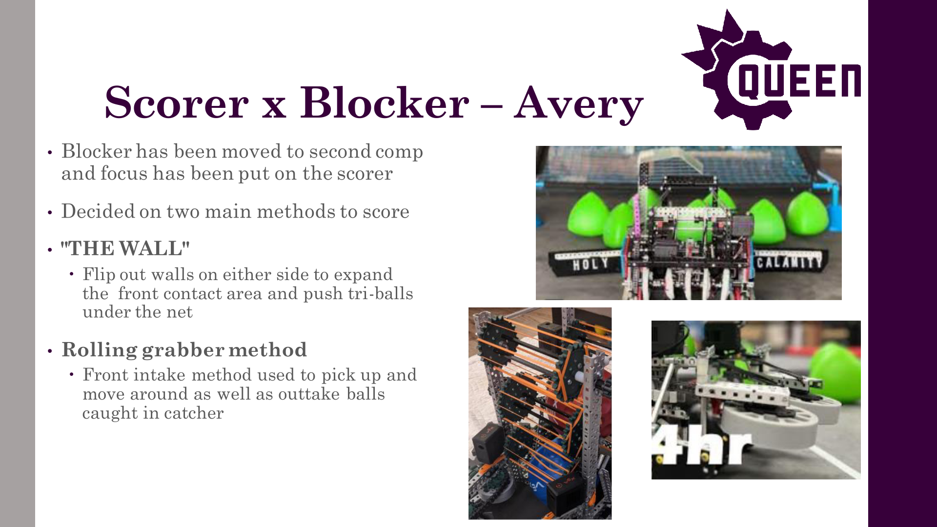
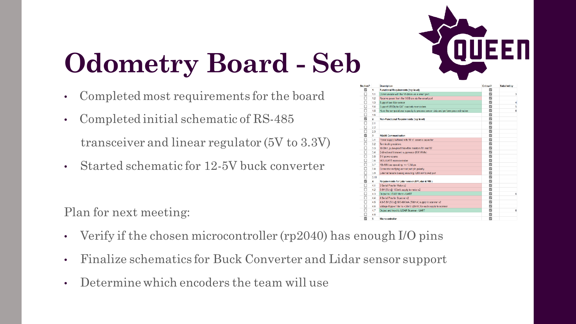

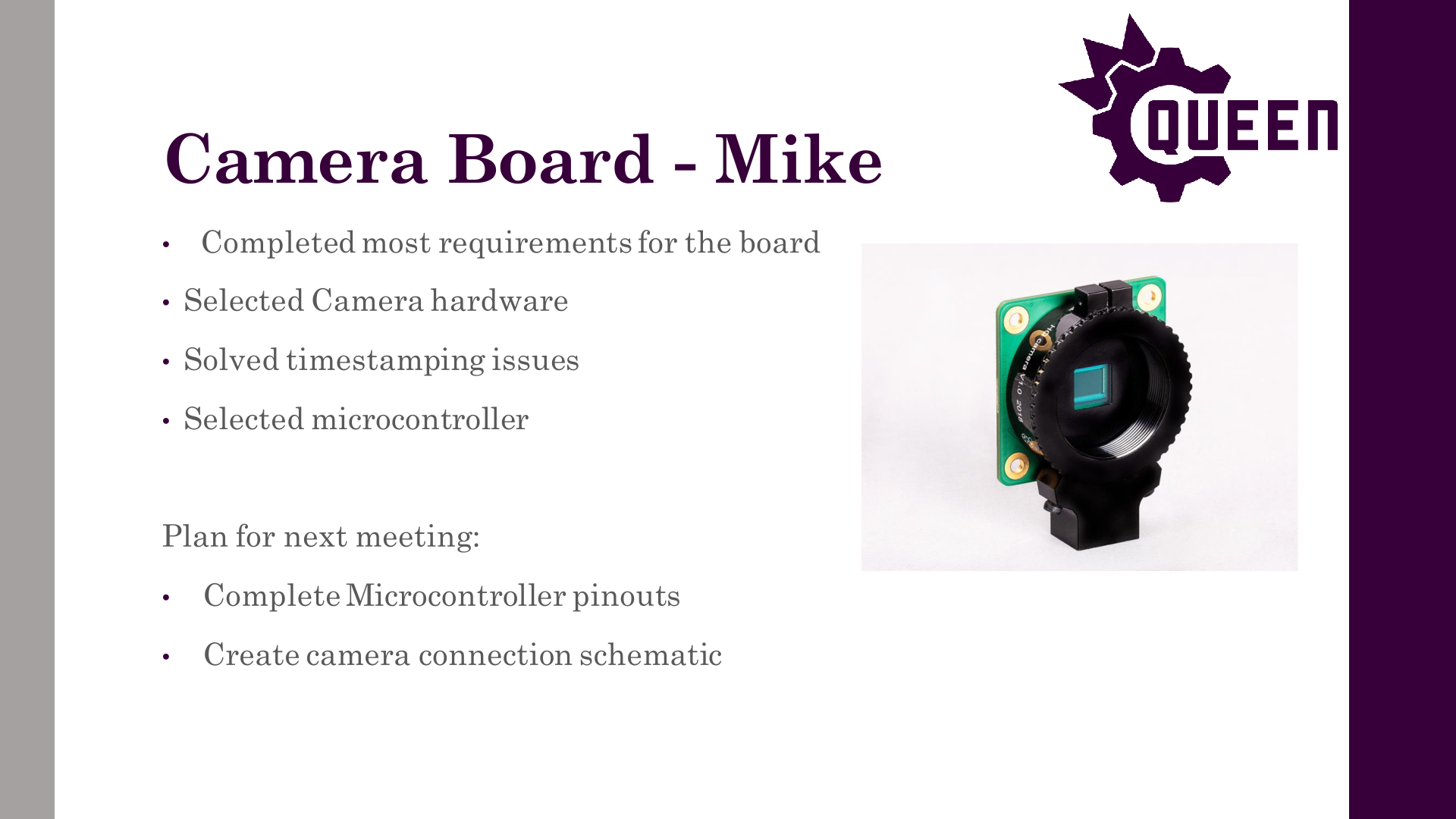


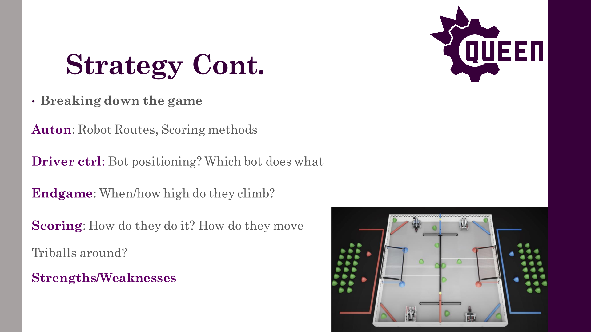

Author: Michael Cassidy
Participants: Everyone
Drive Train Team
Scorer Team
Shooter Team
Catcher Team
Scouting Team
Blocker Team
Other Notes
Odom Board Team
Jetson Carrier Board Team
Camera Board Team
Vex-rt Team
Firmware Team
Documentation System Project
Hardware Workshops
Motion Controllers Team
Computer Vision Team
State Machines Team
Website Team
Author: Michael Cassidy
Participants: Everyone
Drive Train Team
Scorer Team
Shooter Team
Catcher Team
Climb Team
Other Notes
Odom Board Team
Jetson Carrier Board Team
Camera Board Team
Vex-rt Team
Firmware Team
Motion Controllers Team
Computer Vision Team
Robot Subsystem Team
Website Team
Author: Michael Cassidy
Participants: Everyone
Drive Train Team
Scorer Team
Shooter Team
Catcher Team
Climb Team
Vex-rt Team
Firmware Team
Computer Vision Team
Strategy Team
Robot Subsystem Team
Website Team
Author: Theo Lemay
Participants: Everyone


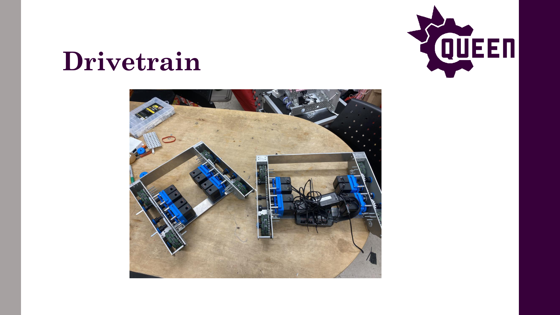
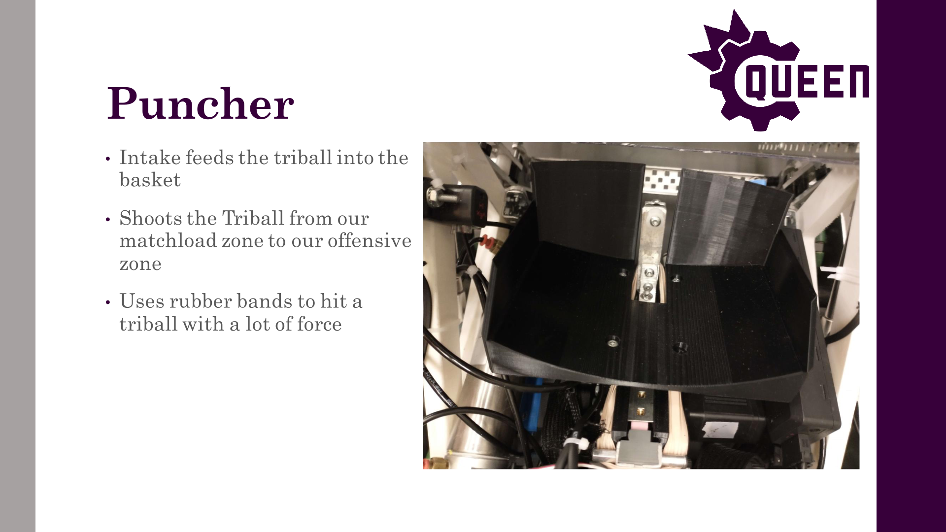
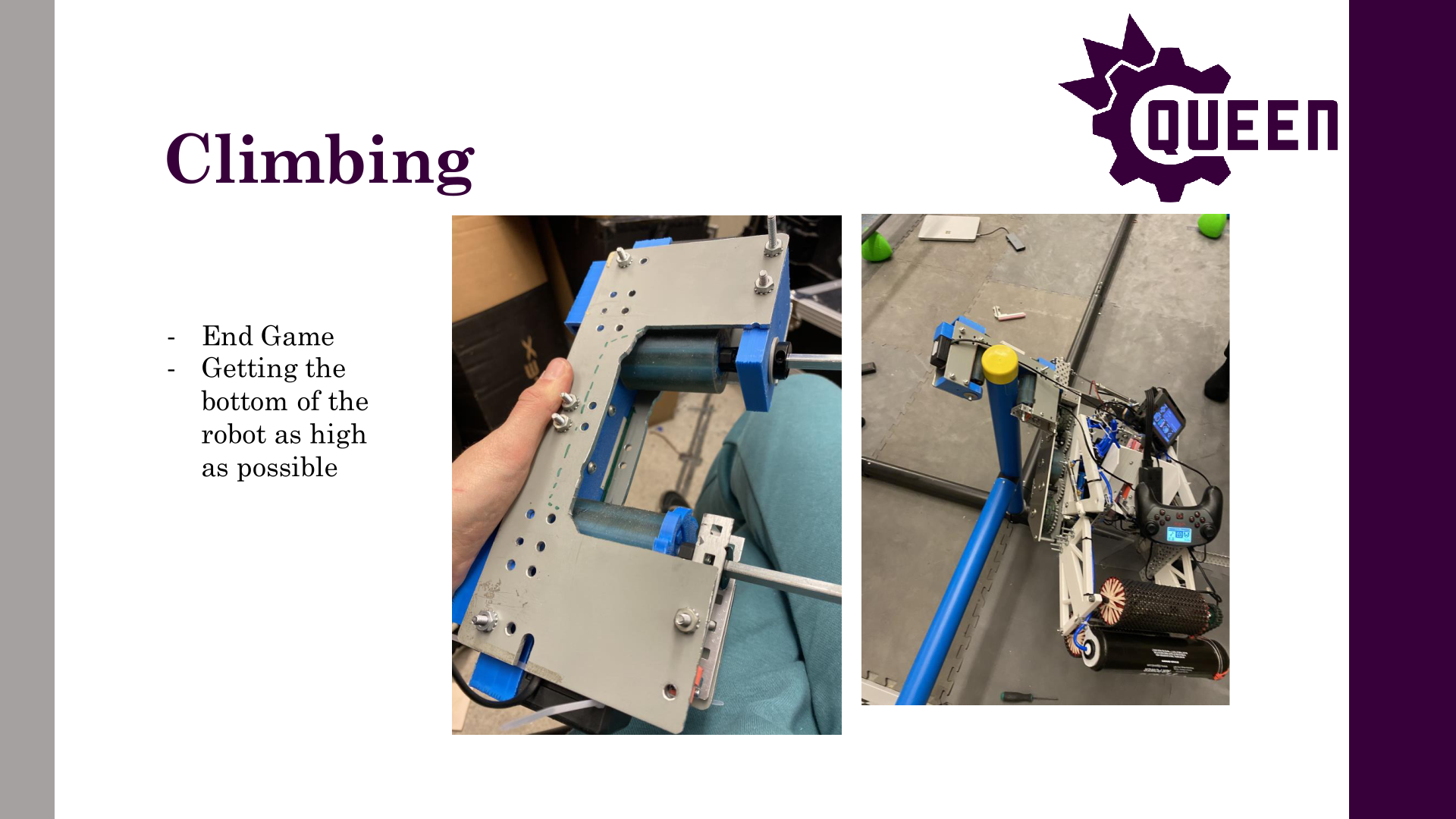
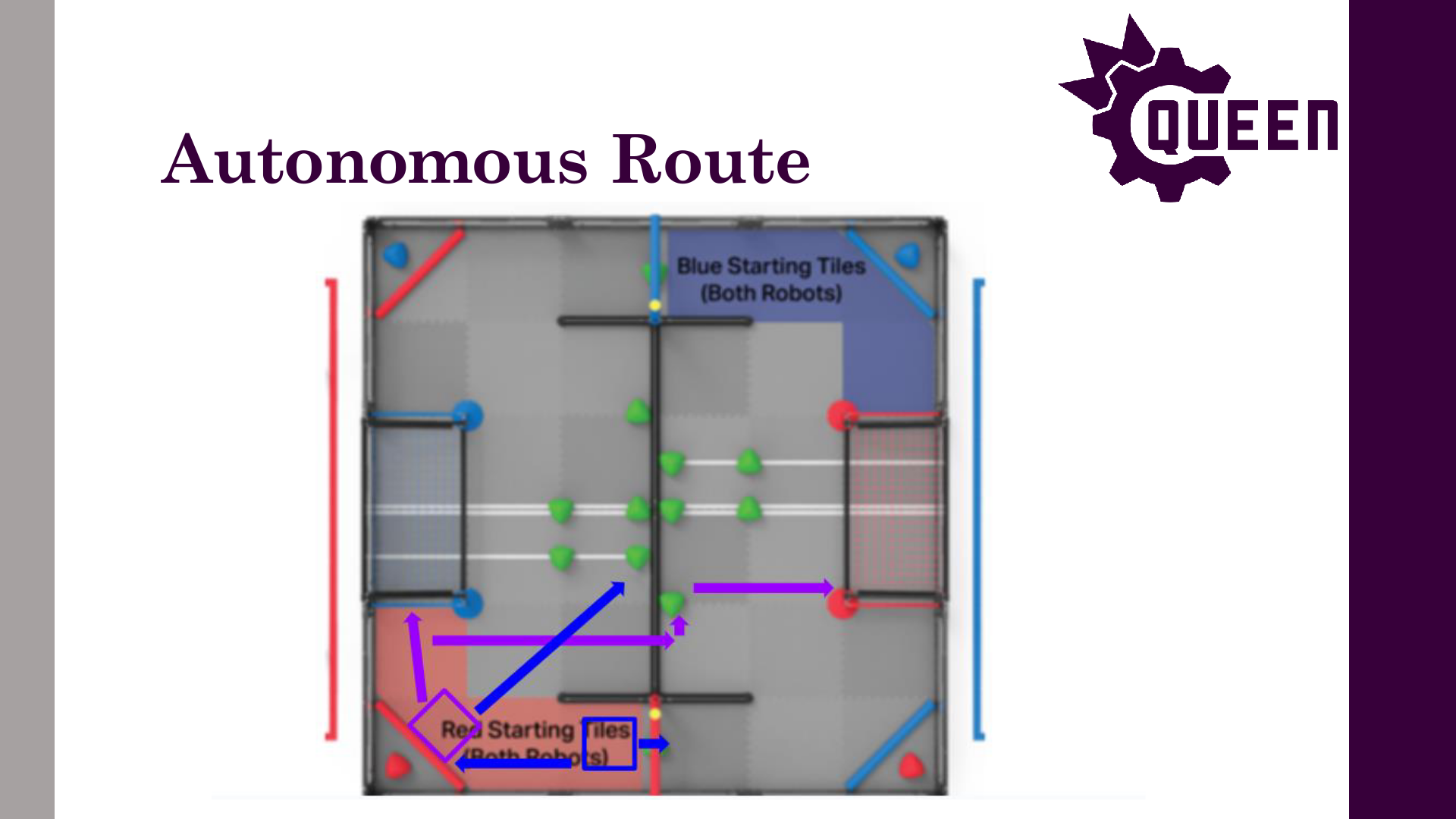


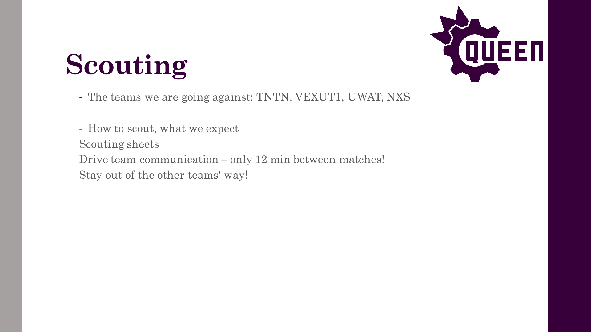

Author: Charles Lapointe
Participants: Benjamin Battye
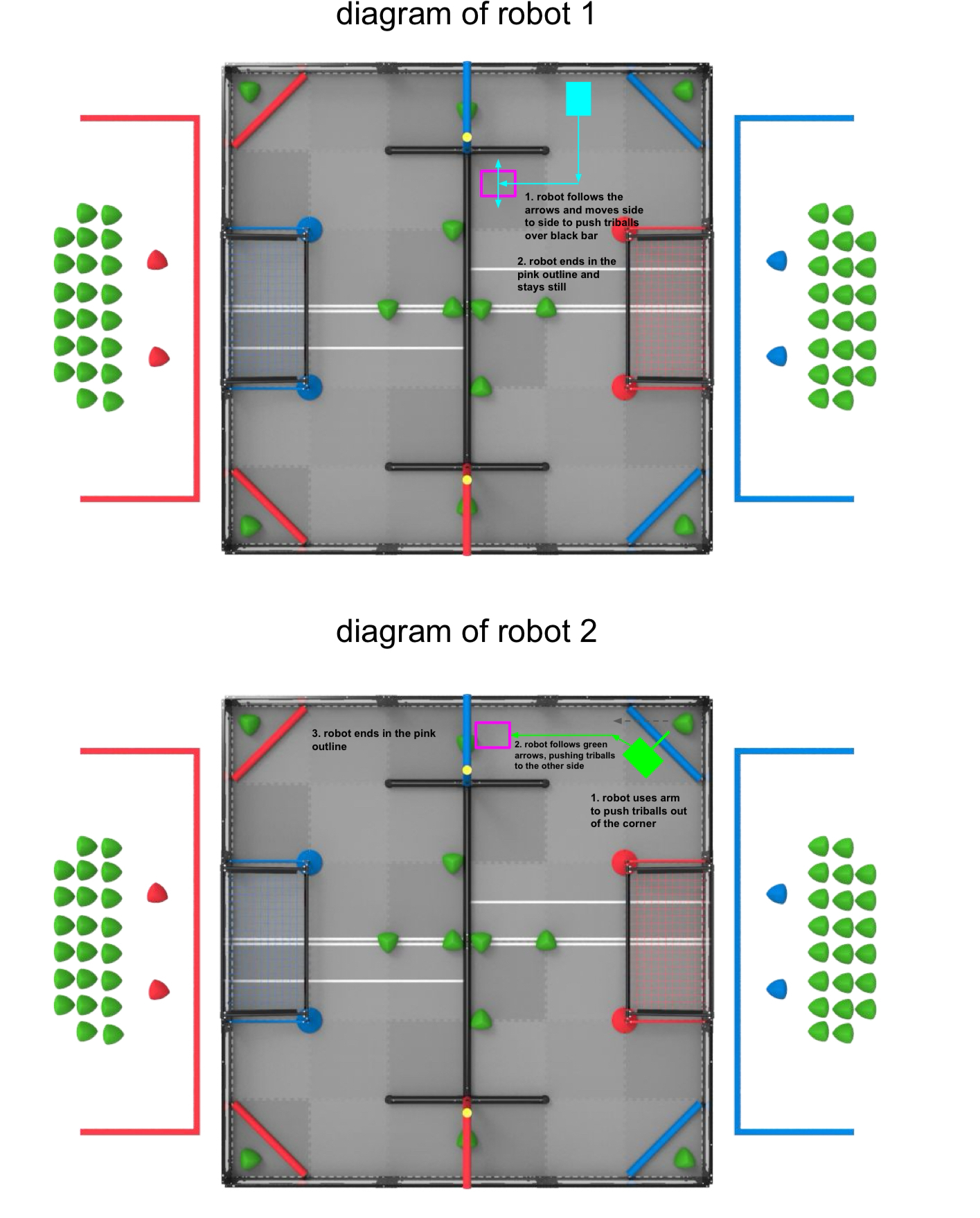
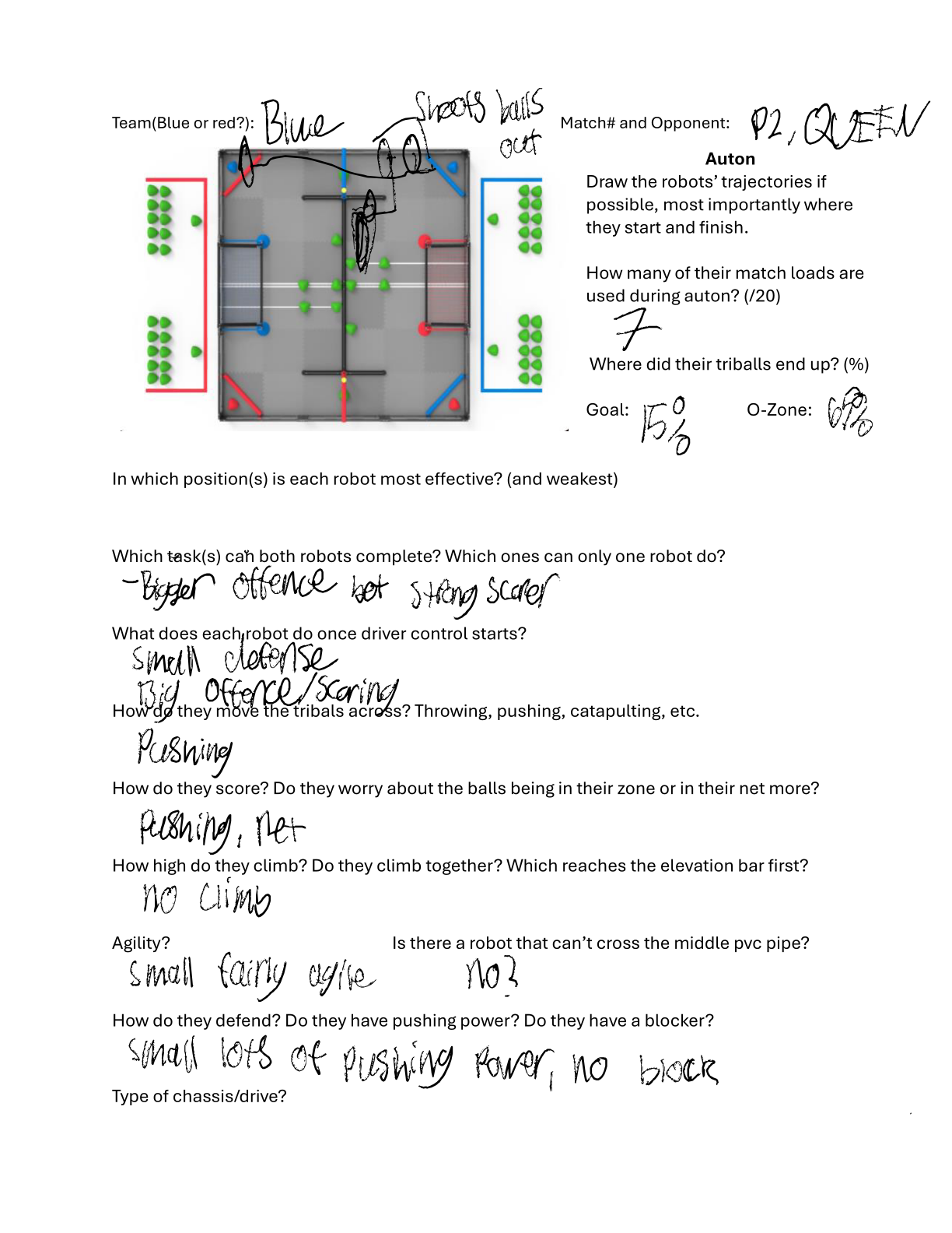
Author: Theo Lemay
Participants: Everyone
Hey everyone! I hope you had a nice weekend, had fun at QRC, and got some experience with the team & vex. I also hope you all gave some thought to what went wrong and how we need to improve. Yesterday, the tech leads got together and discussed what we thought were our weaknesses, and how we want to address them for West Virginia (WV). If ANYONE has any other insights/suggestions, please feel free to share!
Author: Theo Lemay
Participants: Everyone


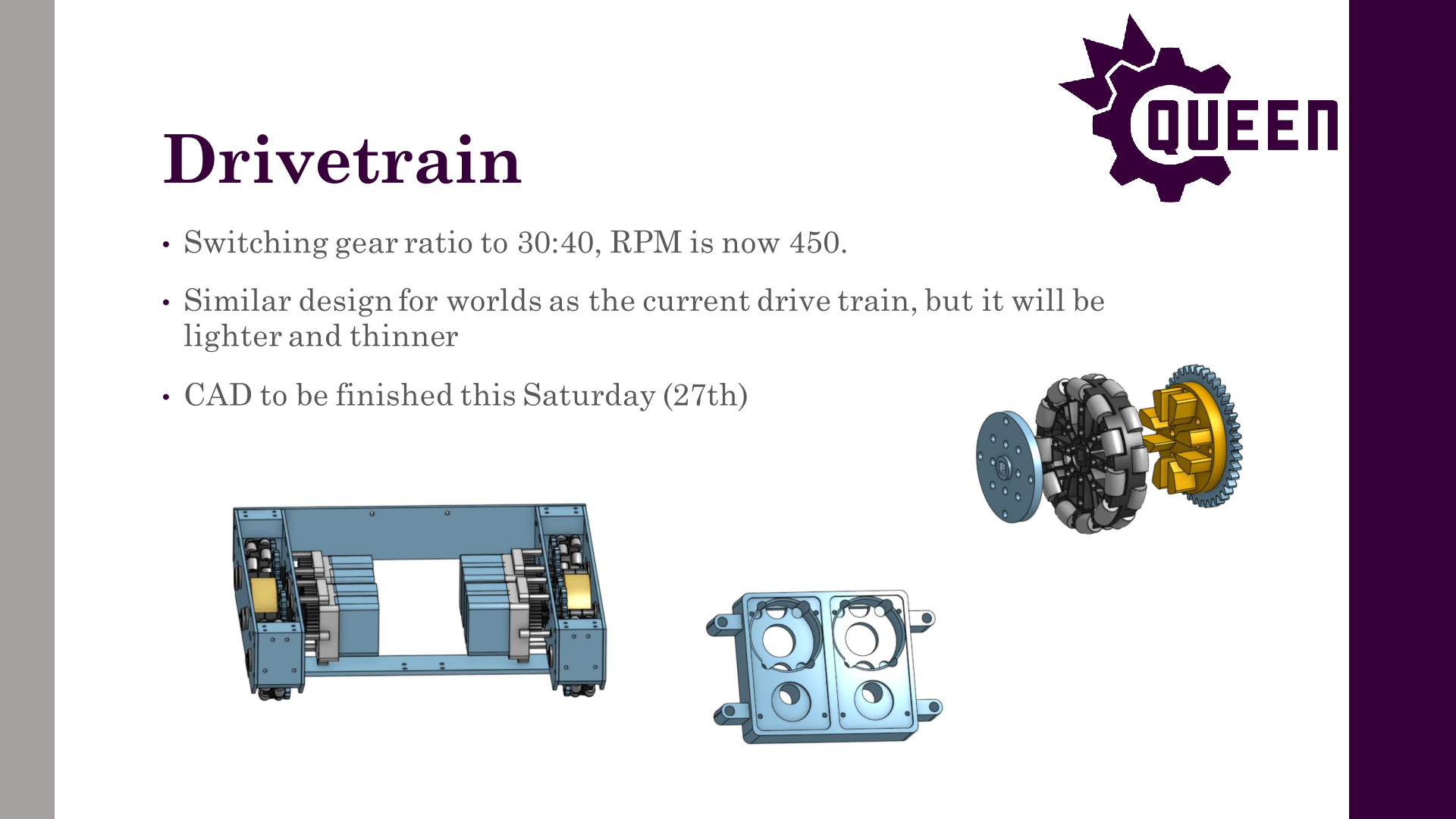
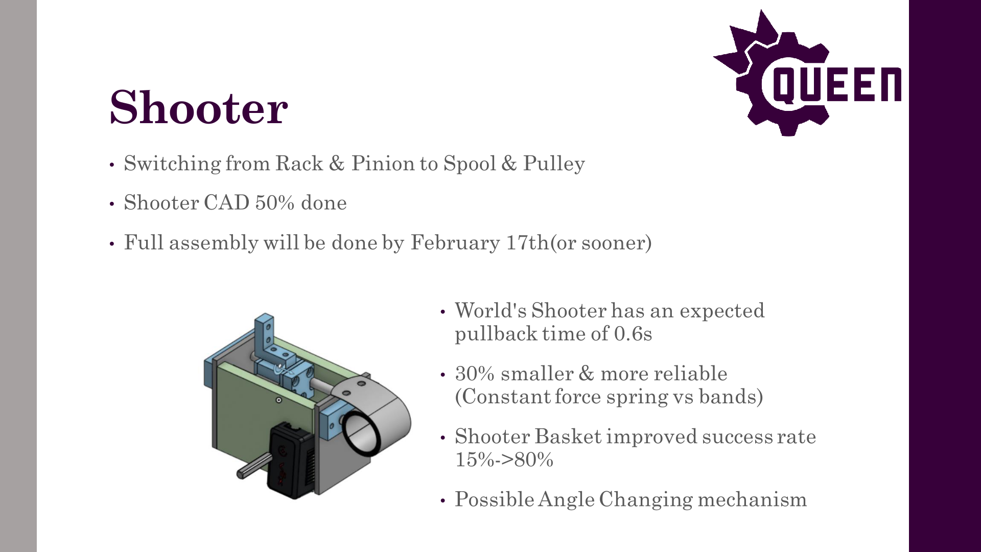
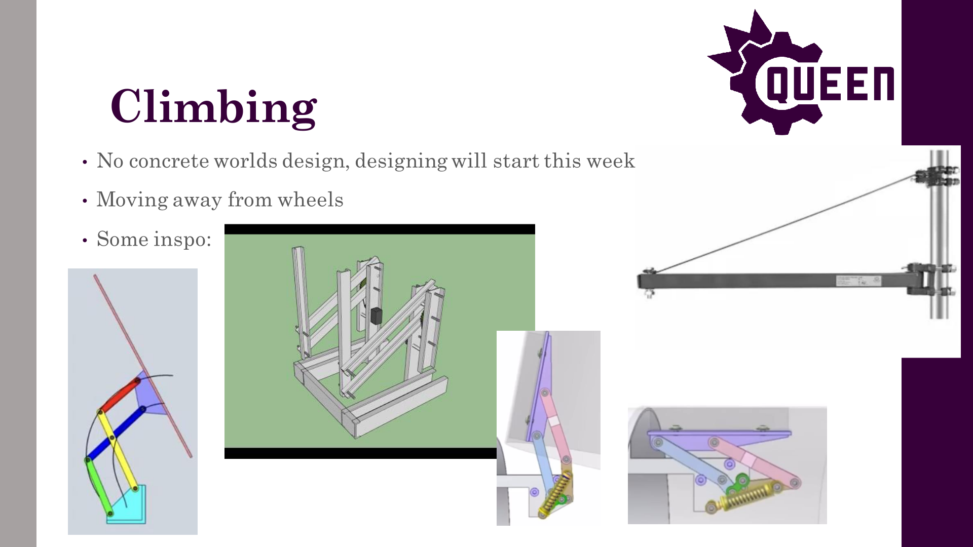
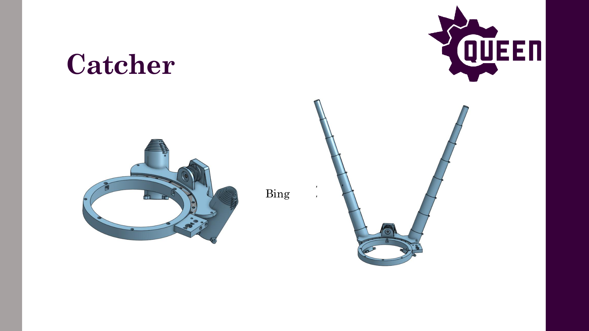
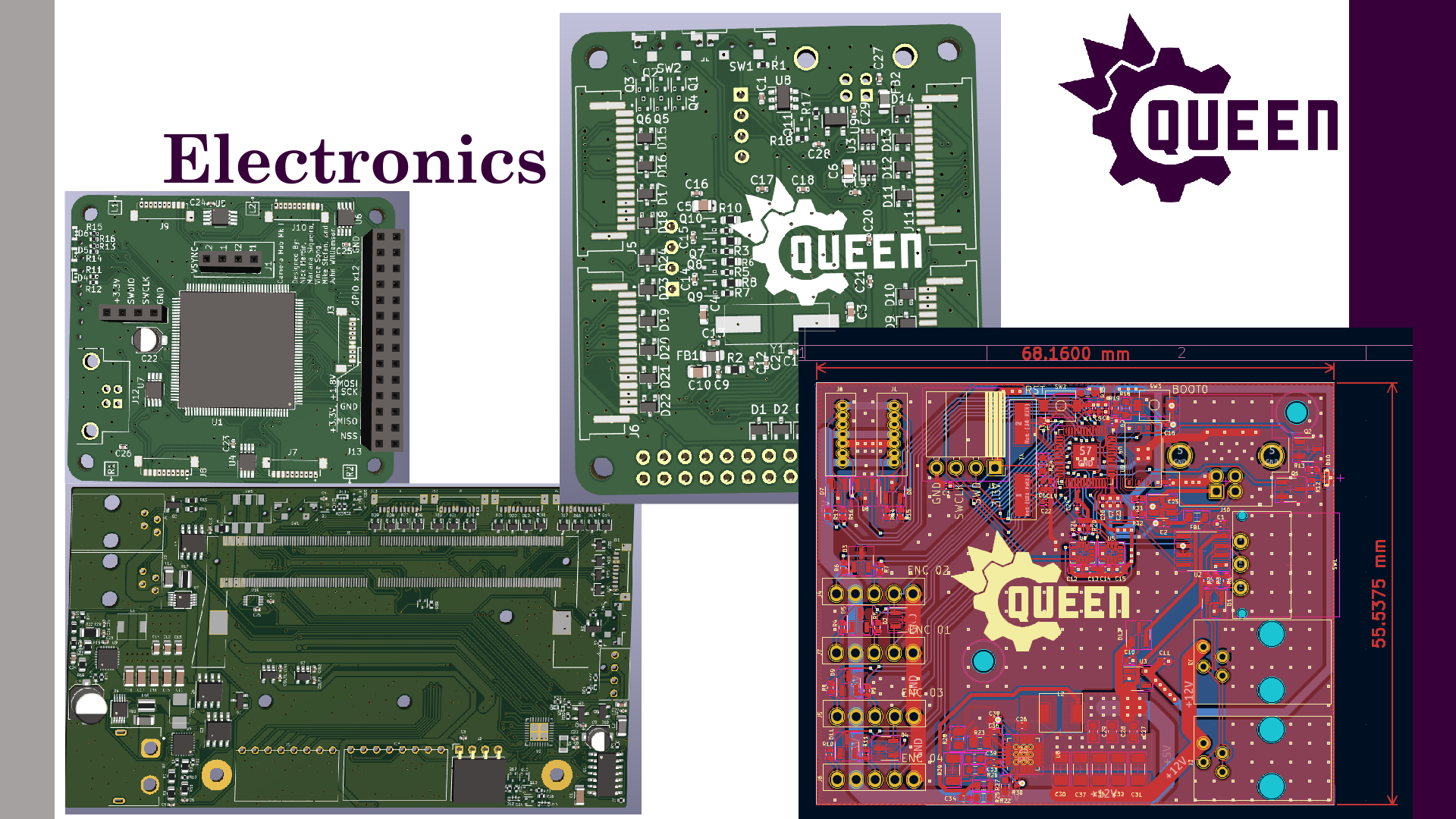


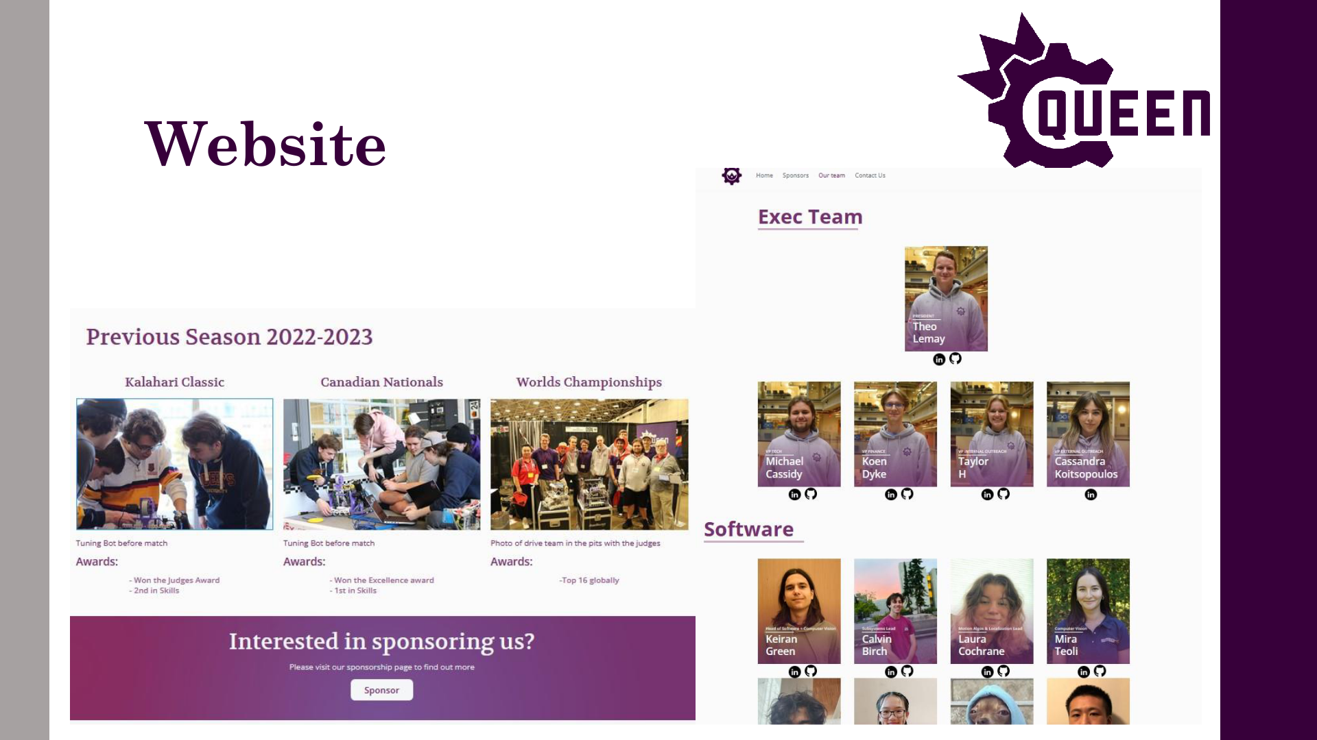
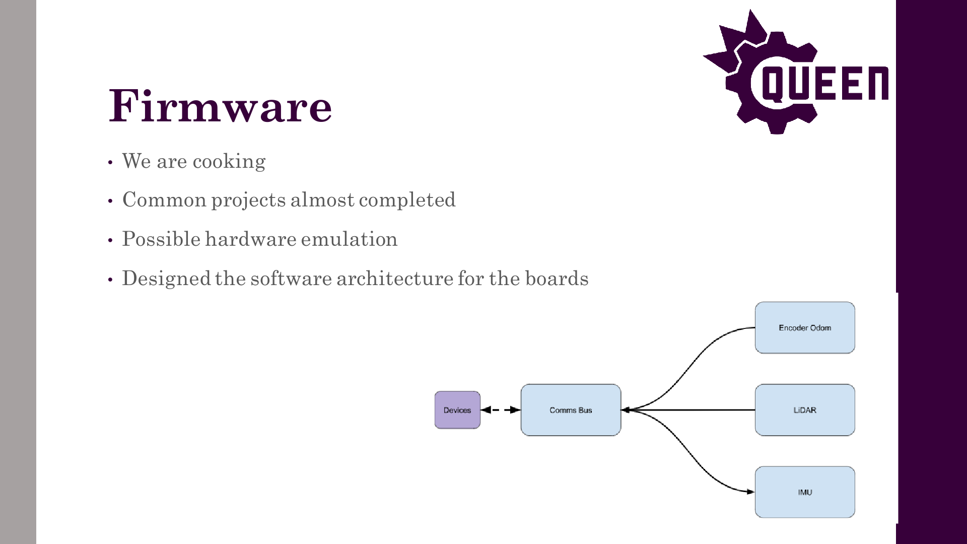


Author: Theo Lemay
Participants: Everyone
https://youtube.com/shorts/-hLpdGjf5C8?si=Ug3jtOLe5pGXspLu (featuring a blurry sms video of how we want partner climb to work)
How to get involved:
Author: Charles Lapointe
Participants: Everyone
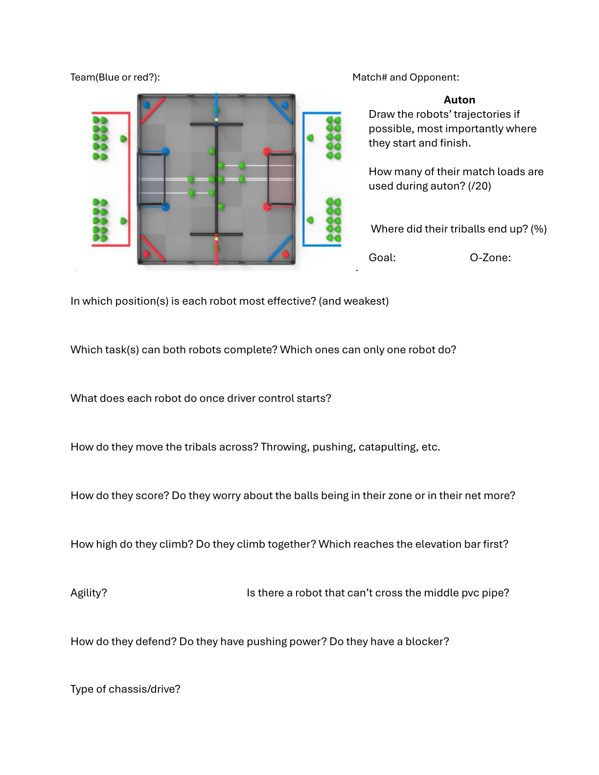
Author: Theo Lemay
Participants: Michael Cassidy, Theo Lemay, Avery McFadden, Mike Stefan,
Will Steedman, Maxim Pletnev, Patrick Shu, Benjamin Battye, Cole
Jowett
Author: Theo Lemay
Participants: Everyone
Author: Theo Lemay
Participants:
Author: Theo Lemay
Participants:
Author: Theo Lemay
Participants:
What is the purpose of this meeting? What do you hope to accomplish?
https://docs.google.com/document/d/12d3hJnsayU3ZOdB1KFOhwPtPbK95zhv2g18vOhHTIf8/edit
“One person can build a hut, but thousands together can build a skyscraper!”
Queen’s University, Kingston, Ontario, Canada
With special thanks to:
![]()
|
|
|
|
| |
|
| |
Welcome to QVEX! I am excited to present the results of our passionate and talented team, and hope you will enjoy reading about our progress thus far!
My name is Theo Lemay, and I am the 2023-24 President of the Queen’s VEX U Robotics Team, otherwise known at Queen’s as QVEX. I’m in 3rd-year Mathematics and Engineering at Queen’s, with a specialization in Systems and Robotics. This year, I’m leading our team of over 80 members to excel in competition, engineering design, and education.
I’ve been doing VEX Robotics for over 6 years, and it has transformed my life and opened up so many opportunities. By taking on the role of President at QVEX, I hope to give back by sparking the same passion in others, and I believe design teams are one of the best ways to do so!
Founded in 2019, QVEX is an award-winning competitive robotics team under the Engineering Society and Alma Mater Society. With over 80 interdisciplinary members from engineering, commerce, and science, QVEX consists of 4 Vice-Presidents, 5 Senior Technical Leads, 20 Technical Leads, and over 50 general design members.
Last year, the team achieved some huge milestones, placing 1st in Canada and reaching quarterfinals at Worlds after starting the season from scratch. This year, QVEX is focused on four key goals, consisting of Competition, Education, Outreach, and Long-Term Governance. While the team has dreams of excelling on the world stage, providing real-world engineering experience and teaching professional design practice is foremost in the team’s mission. For this reason, significant effort is placed to promote awareness of robotics and engineering. Finally, developing a solid foundation and framework for the team is crucial for its long-term success.
The following notebook contains all relevant information about QVEX. I am beyond excited to see the education and innovation we achieve throughout this year’s competitions. On behalf of QVEX, thank you for reviewing our notebook.
Sincerely,
Theo Lemay, QVEX President 2022-2023
The Queens VEX U Robotics Team (QVEX) is an award-winning competitive robotics team under the Engineering Society and Alma Mater Society. With over 80 inter-disciplinary members from engineering, commerce, and science, QVEX consists of 4 Vice-Presidents, 5 Senior Technical Leads, 20 Technical Leads, and over 50 general design members. The team was founded in 2019 to revolutionize engagement in robotics at Queen’s, while also developing a globally recognized competitive program.
In the 2022-23 season, QVEX experienced incredible growth, starting with three core members, growing to over 40 members throughout the season, and finishing with a core of 20 dedicated members who are now all part of the executive team. In one short year, QVEX finished as a quarterfinalist in its first-ever VEX U World Championship, ranked as the best university team in Canada, and won the Excellence Award at Nationals. The amount of passion and talent on the team is enormous, and the team is poised for another year of growth.
In the 2023-24 season, QVEX is focused on four key goals, consisting of Competition, Education, Outreach, and Long-Term Governance. While the team has dreams of excelling on the world stage, providing real-world engineering experience and teaching professional design practice is foremost in the team’s mission. For this reason, significant effort is placed to promote awareness of robotics and engineering. However, QVEX is on track for an extremely competitive year and is estimated to be top 10 in the World, and top in Canada. With the addition of 60 new members and the core of 20 experienced members, QVEX extends a warm welcome to all students, embracing a wide array of skills and experiences.
We pride ourselves on our diversity and the unique skills our members bring to the table, from various ages, races, and genders. We strive to emulate an engineering firm and maintain a family-like environment while providing opportunities for interpersonal development and skills outside of engineering. Aside from technical teams, our team includes members handling finance and logistics, outreach, and sponsorships, from various faculties such as computer science, engineering, and film.
QVEX strives to create well-rounded engineers, capable of working well in both a team environment and as an individual, who will be able to apply new skills to real-world engineering projects. This is done by giving students equal opportunity to contribute and learn, regardless of previous experience and knowledge. We seek to create a passionate environment where all members can give input, develop soft and technical skills, and feel comfortable in an inclusive community.
The president is hired on a yearly basis, and is responsible for selecting the Vice-Presidents (VP), and project managers (PM). In addition to this, the president is the main connection to the faculty and engineering society, runs general meetings, aids in robot design and construction, and assists VPs and PMs with tasks such as connecting with a sponsor or taking on additional work from a member too busy to complete their project.
Below the president fall the VPs, who are responsible for selecting and managing the PMs. Similar to the president, VPs must apply for a job posting and go through an interview process in order to secure the position.
Project managers are the day-to-day managers of the team. They are chosen based on an application process and facilitate the production of the robots. PMs break down the project into tasks, supply tasks to their members, and maintain the project timeline.
A visualization of this structure is shown below.
Team communication is spearheaded on Discord, an online social platform allowing the team to communicate via voice, text, and video, along with supplying the organizational capabilities to properly break down the team structure and the various projects the team tackles. Team members are expected to check the server at least once a day, to stay up to date with the team’s progress, and any important news regarding the team.
If something arises that the team president deems highly important, an update will be sent via email in addition to signalling the team on Discord. When signing up for the team, members provide their student email, which is then put on a mailing list, for important updates.
Communication does not solely lie within the team, it expands to teams across the globe. This is done through social media, such as YouTube, and Instagram. For example, QVEX continues to release tutorials and documents to aid other teams in the creation and improvement of their robot, alongside other teams to help us improve our own.
To manage the design process of such a large team, a novel notebooking approach was developed. It consists of four parts:
An interactive view of the database is available at: https://queens-vex.fibery.io/@public/Notebook/.
A screenshot of the database is shown below:
When subteams have a meeting, they fill out the meeting log form at http://log.qvex.ca/, also shown below.
The subteam can then describe what happened during the meeting. This meeting log gets added to the database, and is also summarized by AI and sent to a channel in the discord server.
Finally, a script is triggered which runs a cloud worker that compiles the document together and produces a rendered PDF.
|
Theo Lemay President 3rd-year Applied
Mathematics & Engineering
Koen Dyck VP Finance 3rd-year Applied
Mathematics & Engineering
Taylor Hambleton VP Communications &
EDII/AS 3rd-year Applied Mathematics & Engineering |
Michael Cassidy VP Tech 2nd-year
Computing
Cassandra Koitsopoulous VP Outreach 3rd-year
Engineering Chemistry |
VEX Over Under puts two teams, each with two robots, on a 12’x12’ field, competing to score the most points. The field includes 60 triballs–4 as preloads, 44 as match loads, split between the teams, and 12 beginning on the field. It also contains two elevation bars, four matchload goals, and two goals, all split between the teams. The game is divided into the “Autonomous Period” and the “Driver Controlled Period”. Points scored during the autonomous period carry over to the driver control period.
During the autonomous period, which lasts 45 seconds, points are awarded at round completion if specific requirements are met. A point is awarded if a team scores an alliance triball and contacts the elevation bar. A bonus of 8 points is awarded to the team that scored the most at the end of the period.
The driver-controlled period, lasting 75 seconds, has the team trying to outscore their opponent in multiple ways. Five points are awarded for each triball scored in a goal, and two points are awarded for each triball in the opponent’s zone. Finally, points (up to 20) are awarded for each of the four tiers of elevation.
The field features two opposing scoring zones separated by a roughly 3” tall bar, each with two zones for teams to match load.
The match loading zones are separated from the field by a 30” long 2.5” diameter bar, from which bots cannot cross but can intake triballs.
Scoring zones are connected by two gaps under the elevation bars, which are 11.63” tall. To access both sides of the field, a robot must be under this height or capable of driving over the 3” bar.
White tape separates the left and right sides of the field and marks the area that robots can access during the autonomous period.
Triballs can be pushed under the roughly 5.78” tall goal post, which counts as 5 points. Other triballs in the offensive zone count as 2 points, and alliance triballs count as 5 points to the team of their colour, regardless of which net they’re scored on.
The two posts fixed to the field can slide up, meaning some force is required to score a triball.
Triballs can only be removed if both robots of the scoring team are in the defensive zone. One of these robots contacting the middle bar counts as having it in the offensive zone, meaning the team can no longer un-score triballs.
Towards the end of the driver period, robots can climb their elevation poles, and the score given is based on the robot’s lowest point at the end of the match.
Points given are compared with the highest climb being awarded 20 points, the second highest getting 15 and so on, down to 5 for the lowest.
Two robots at the same climb height are awarded equal points, with the next highest climb being awarded one tier lower.
Robots that do not climb are not considered while scoring the climb.
Robots cannot contact robots touching the ground or the golden bar cap on the vertical elevation bar.
Triballs are a constant-diameter pyramid-like shape with rounded sides and a rigid plastic exterior that weighs approximately 110 grams.
Triballs are scored when two of the four corners are under the outermost part of the net, as shown to the right.
During skills, the team’s alliance balls can be placed at any point on the field if unscored.
Once we completed the initial analysis of the game’s field elements and got a feel for how to get practical scoring underway, the team had some meetings to discuss potential strategies. The main factors affecting said strategies were the game’s autonomous phase and the triballs’ movement.
Early on in the season, it was desired to get an excellent autonomous strategy to get ahead of opponents once driver control started. Since this year’s game’s scoring elements mostly have to be introduced into the game as individual match loads, it was determined that a large portion of those triballs should be introduced during the autonomous phase of the game so that the bots can focus on other objectives during driver control. There are 22 triballs for each team as match loads, so ideally, above half of that will be depleted and scored during the autonomous phase.
Another deciding factor for our bots was how moving triballs would be done. From what the field looks like, the two viable options are through the air over the middle PVC barrier and pushing it through the outside beside the elevation bars. So the team initially went with a puncher shooting design to shoot the triballs from one zone to another, effectively going over the middle barrier. This will be complemented with one of the bots having a catcher mechanism, ideally catching every triball in the offensive zone shot from the shooter bot and out-taking the triball in the net to score top points. On top of that, our robots will have some side wings that act as a plow to push triballs on the outside towards the goal. This is to give variability to our strategy in case one method becomes more favourable. Other teams have proven these strategies viable with their mechanisms, but the team hopes to do so better.
Two tables were made based on our experiences at competition with how our robots performed and strategies that we have seen other teams implement. The tables outline required features for world bots based on designs we plan on implementing and possible changes that need to be made. Some decisions can be seen in other subteam sections with weighted evaluation matrices to match.
Going into this season, our goal was to expose a new set of creative members to all aspects of VEX, and part of this meant starting with a relatively simple design. Hosting QRC and having the team structured with many smaller sub-teams significantly helped with member engagement. It also significantly helped with the progress of the robots, allowing for more iteration and, therefore, more consistent designs. The lack of experience with VEX proved to be a benefit as the designs for the world’s bots are very original and take advantage of mechanisms and coding that rarely see use.
Discuss our world goals (ambitious) vs competition goals (ease of implementation) with a decision matrix.
The scouting side of strategy is critical to the team’s success, as it gives our drive team a lot of knowledge of their opponents before our matches. As they get played, scouts will use the scouting sheet as an aide-mémoire to build strategies against their corresponding team and provide strategy leads/drive team members a visual representation of robot routes/functions, providing a deeper explanation of the opponent’s behaviour. The scouting sheet was made with a vision of including most of the questions the drive team would have regarding strategy for scouts to think about while watching matches. For example, the figures below show the scouting sheet, followed by two examples of how one of our scouts drew out an opponent team’s autonomous routes for both of their robots.
QRC Analysis & Goals
For many reasons, the Queen’s Robotics Cup challenged the strategy aspect of the team’s functionality. The scouting sheets were made, but as the cup was hosted at our university, many team members attended, and since many of them wanted to be more involved with the team, they were scouts. It was to the point that there were twenty scouts for only five teams at the competition, and it was too much to process in such a short time. Multiple other factors include there wasn’t any primary constructive system in place for scouting to be communicated to the drive team, and given it was a small tournament, there wasn’t much time between matches, so the drive team prioritized the robot’s maintenance with our pit crew. Another thing to consider is that the early stage of the season meant our robots were far from perfect, and they faced many challenges during matches, like the intakes not working, some pneumatic functions failing, our autonomous strategy having some malfunctions, etc. It made it hard to visualize a concrete strategy without our robots giving us a taste of our capabilities.
To this point in this year’s game, there were few defined strategies to watch out for early in the season, meaning we didn’t have a good idea of what our strategy had to accomplish. Paired with the technical malfunctions, our biggest priority at QRC became learning how teams would play and what we could do for future competitions.
Have a bot under 11” to transfer triballs under the elevation bar and stop other teams from doing the same.
Playing defensively makes scoring exponentially harder for other teams and gives your team more opportunities. It can be accomplished with more robust drivetrains and bigger wings.
Clearing your zone of triballs quickly allows your defensive bot to match load and put more pressure on their team’s defence.
There was no need to commit more resources to the climb; having an A climb would keep us competitive.
The most significant oversight was how teams would use the gap under the elevation bar to funnel match loads into the scoring zone consistently. A bot under 11” tall allows for a much more consistent method of transferring match loads, particularly in earlier competitions with less advanced robots. Knowing when to match load and being able to play consistent defence was also crucial to success in this competition. We learned that most strategies to this point revolved around having a bot that could score match loads in the offensive zone.
Compared to QRC, the West Virginia competition went a lot better in every aspect. There were lots of conversations about what to improve in terms of strategy and scouting for this competition, including a new member of the drive team working with the strategy lead to get a constructive and clear plan for the drive team’s comprehension. Thankfully, there were also longer times between matches compared to QRC, so the drive team had some time before every one of our matches to have a little huddle to make a strategy. With only seven scouts this time, communication wasn’t cluttered or interrupted. Everyone knew who to talk to and,
most importantly, when. The fact that we had much-improved robots got us 2nd in the competition/skills and a ticket to the world. For this competition, once the match schedule came out, we mapped out times to meet with the drive team to make some strategy and let the drive team know how the other robots were functioning and their movements.
Learning from QRC, we understood better the importance of having a very defensive bot, which meant lower-scoring games but many more wins. Refining the intake and puncher mechanism helped us have an edge coming out of autonomous, meaning we could more efficiently transition into clearing our zone and pressuring theirs. These improvements resulted in a second-place finish, world qualification, and a more impressive skills score.
Having identical bots necessitated developing a more efficient method to cycle between match loading and scoring. We did a great job at defence, which didn’t leave much for the offensive bot to do once the scoring zone was clear.
Improving our autonomous period would mean scoring more triballs rather than leaving the offensive zone to be cleared by their defensive bot.
Match loading can also be done as the opposite team is going for their climb, which can be capitalized on if they have a slow climb.
After our successful competition in West Virginia, there was a meeting to talk about how things went at the competition, and overall, the team was happy. However, there is still room for improvement on the strategy side. The drive team found that the strategies provided were not as intentional as expected and more observation-based, meaning we need to be more precise with methods for our robots to win even more. For example, when one of the robots was defending, the other robot had nothing to do except for an uncontested match load zone. Our offensive robot had nothing to do once all the balls were gone, losing the precious momentum built up to that point. With that being said, the strategy will be a lot more precise at worlds, giving each robot specific tasks to counter the opponent’s robots throughout the match.
During the 2023-24 Over Under season, the mechanical team is roughly split up into 5 sub teams, including:
Each sub team is responsible for the end-to-end design and manufacturing of their subsystem. This section introduces each subsystem, its goals, its design process, and its timeline.
|
|
|
|
| |
Requirements: the drivetrain subteam is dedicated to creating a mechanism that can:
Drive over the center bar.
Fit within the volume specified (15” × 15” and 24” × 24”)
Use a maximum of eight VEX motors
Maneuver quickly and be agile in a game setting
Push opponents around and be strong enough to prevent being pushed
Allow space and connection points for the other subsystems (catcher, shooter, etc.)
Pontoons: With the initial decision of a tank drive, including pontoons as part of the frame seemed feasible for both the strength and rigidity of the drivetrain. These pontoons house the wheels as well as the gears connected to the motors to provide shielding from any bots or other obstacles. They consist of four identical trapezoidal aluminum plates, which are connected in parallel in pairs, each making up one pontoon (two for each side of the bot). They have all the necessary holes to connect the driving axles and the gear axles to drive the bots. Still, they also hold some of the essential connection points of the drivetrain to hold it together and to attach other elements of the robot. To hold the pairs of plates together, thick and rigid metal blocks are situated between the plates at the front and back.
Motor Mounts: On the inside face of each pontoon are two sets of motor mounts. These motor mounts hold two motors together and must match the motor + casings’ profile. To do this, measurements from the motors and casings with all necessary dimensions were taken so the mounts could fit within the motor profile with minimal room for the motor to move around. The design also made sure that there were the necessary holes such that the motors could be directly attached to the mounts and the mounts could be attached to the pontoons, both with screws.
Geartrain: A geartrain, or more technically, a transmission, couples motors together and outputs torque to every wheel on the pontoon.
Cross Braces: Cross braces were used to connect the pontoons and hold the various added subsystems on top and behind the drivetrain. Because they were the anchor to almost the whole robot, they were designed to be strong and allow for other subsystems to be attached.
Design Process: The initial design considered discussing and weighing the different drivetrain types regarding maneuverability, speed and other factors (see WEM below). It was decided that the tank drive was best for the first half of the year as it was relatively simple but powerful, allowing us to push other bots around. Many iterations were done throughout the design and CAD process, changing up some of the parts above. Once the CAD and manufacturing were done, we tested alongside some software teams to test our drivetrain and their code simultaneously. We used the QRC competition as an opportunity to test and understand the flaws of the design. Using the main issues we spotted during this competition and in preparation for Worlds, the drivetrain team split up to work on the 24” tank drive and the 15” drivetrain. Using what we learned, many iterations were done to allow our robots to be more agile and able to cross the center bar.
All standard drivetrain styles were considered for the robots. These basic designs have been vastly explored in previous competitions. The possible designs are as follows.
Tank Drive: This design involves a forward-facing omni wheel in each corner and a traction wheel in the middle. Eight motors, four per side, would drive the wheels. The design generates a lot of torque but cannot strafe (move sideways). However, the design’s basis makes it difficult for opposing bots to push it from the side.
X Drive: An X drive has four omni wheels, all at 45-degree angles, resulting in high maneuverability and speed. This design would make a highly nimble robot that can quickly get anywhere on the playing field. However, it may not drive straight when there is an imbalance of weight.
H Drive: H drives incorporate five omni wheels, one forward-facing in each corner and one across the center. The center wheel allows the robot to strafe but also allows an opposing robot to push it from the side. The design is still fast, but the wheel in the center can be challenging to access, presenting some maintenance problems during competitions. This also results in at least one extra motor to drive the center wheel.
Square Drive: A square drive has four forward-facing omni wheels, one in each corner. This is the most basic drivetrain, but it is easy to push and generates an average amount of torque.
Swerve Drive: This design uses two motors to rotate and turn an omni wheel on each of the four corners. It has the benefits of a square drive and an x drive as it can change the orientation of each wheel when necessary to vary speed and torque. While pushing is easier than a tank drive, it can turn its wheels to make pushing harder than a square drive.
The generated concepts were then evaluated using a weighted evaluation matrix, which can be found below. The following criteria were weighted based on their criticality to the design’s functionality.
Speed: This criterion looks at the speed that the drivetrain can produce. This category is important because it will dictate how quickly the drivers can react to the other team during the match. A quick reaction to the other team will optimize the robot’s ability to score and defend, which is why it receives a weight of 4.
Power: Power is the evaluation of the drivetrain’s ability to push other robots. This can be estimated through the torque generated by the wheels. This had the highest weight as it was determined that it was very important that our robot would be able to overpower other robots and also make it over the center bar.
Strafe: Strafing is the drivetrain’s ability to strafe back and forth. It is low-weight because it is less important than maneuverability. Since it is not as crucial as maneuverability, it receives a weight of 2. If a drivetrain can not strafe, it gets a score of 1.
Maneuverability: The ease with which the robot can turn. This category has a moderate weight as the robot needs to be able to maneuver precisely during matches. It also allows the drivers to react quickly to the other team; thus, it receives a weight of 3.
Maintenance: This criterion evaluates the ease of maintenance on the drivetrain, including frequency and accessibility. This is an important category as there are many mechanisms and little time between matches, so the pit crew must be able to perform drivetrain maintenance quickly with few complications.
Innovation: As part of our overall goal, an innovation factor was incorporated into the selection process. It evaluates the difficulty of the design and how its incorporation will set our robot apart from other teams. It is not weighed heavily because functionality is still the most critical aspect of the design.
Below is the completed evaluation matrix indicating each criterion’s scores for each design.
Criteria | Weight | Tank Drive | X Drive | H Drive | Square | Swerve |
Speed | 4 | 4 | 5 | 4 | 4 | 5 |
Power | 5 | 5 | 1 | 4 | 4 | 4 |
Strafing | 2 | 1 | 4 | 3 | 1 | 5 |
Maneuverability | 3 | 3 | 5 | 3 | 3 | 4 |
Maintenance | 3 | 4 | 2 | 2 | 5 | 1 |
Innovation | 1 | 2 | 4 | 3 | 1 | 5 |
Total |
| 66 | 58 | 60 | 63 | 70 |
The tank drive was initially selected due to its high scores in power and speed. It allows our bots to push others around while being relatively maneuverable. With an easy manufacturing process and lower maintenance issues, the design was optimal for implementation in the short time frame of early competition.
However, this was re-evaluated after testing, where it was found that there were more strategic uses for having a robot that the other team couldn’t move. It was found that having two different drivetrains for the robots would be helpful. The 24” would maintain a simple tank drive to hold its ground, and the 15” would use a swerve drive, which allows it to maneuver easily. However, the swerve drive has more complicated maintenance. The x-drive was discarded because it would not reasonably be able to climb over the center bar.
Rough Prototype: Very early in the design process of the drivetrain, within the first few meetings, a very temporary drivetrain was made so that the software teams could begin some learning and testing for their components. It consisted entirely of VEX parts, including some scrap VEX metal, old tires, and parts from previous bots. While not very strong nor effective, it taught the team some very early requirements and plans for the future drivetrains to be built. It also allowed the new members to get involved and learn how to make
a drivetrain. The main takeaway from this very early prototype was the importance of the strength of the drivetrain frame, as this one was very flexible, which could cause the robot to drive slightly askew and would make it easily pushed around.
QRC Drivetrain: The second generation of drivetrain was planned for the first competition in January. Due to time constraints and some of the new members’ inexperience, a six-wheel tank drive seemed best suited for the early competition. The main advantage that a tank drive offered was excellent strength when driving forward. This meant that, if done correctly, all the motor power would be directly transmitted to the forward motion of the robot. To get the full advantage of the tank drive, one of the main components where the wheels. For the turning capability, the robot needed omni wheels, but with a six-wheel, only four of these wheels needed to be omni wheels, leaving two wheels that could help with traction. VEX has wheels with a wide, flat rubber lining, which offers significantly more traction than the omni wheels. However, the team cast our wheels, allowing even more traction and resistance to being pushed around.
The drivetrain’s framework, which included the pontoon parts and the braces, was made from recycled aluminum. This had two distinct and obvious advantages over our rough prototype. Firstly, these were going to be significantly more robust when compared to the rather flimsy VEX metal parts. They were rigid and would protect the inner components, such as the gear train, the wheels, and the motor mount. In addition to being strong, being custom-made from aluminum sheets would allow for custom hole placements for specific attachments, and we were not limited to the grid structure of the VEX metal. This new drivetrain also required rigid and secured motor mounts to hold the motors in place while in operation. However, due to them being hand cut over them being machined, this required many hours of sanding and polishing.
Post-QRC Drivetrain: While the drivetrain built for Worlds worked consistently, it still had some flaws that needed to be addressed. Our QRC drivetrain’s main issue was that it could not cross the center barrier. This was a very big weakness as crossing the center barrier is the quickest way to cross to the other half of the field, which, during both the autonomous and driver period, can allow for quicker points to be scored than going around the center barrier. To resolve this issue, the angle at the front of the pontoon was steepened so the front wheels could grip the barrier better and get over to the other half. Another issue found during the previous competition was the difficulty of replacing and fixing components within the drivetrain. The pontoon design was almost too effective in protecting the inner components, as even the team could not quickly access the wheels and motors. We considered some ideas, such as a hinge mechanism to unlock the face of the pontoon for easy access, but this could severely hinder the desired structural integrity.
Worlds Drivetrain:
The worlds drivetrains are split into two different types. Given that we got the qualification for Worlds at the WVU competition, we developed a swerve drive for the smaller 15” drivetrain for more maneuverability for the high-level competition.
24” Tank Drivetrain
The 24” drivetrain (pictured above) resembles the Post-QRC drivetrain. The main ideas of getting over the center bar and accessing the motor and drive components were carried through with minor improvements. During the time after the QRC competition and the WVU competition, the QVEX team gained valuable access to the McLaughlin Machine Shop on campus. This allowed the team to make many iterations in the material used for the drivetrain frame. This consisted of machining the necessary aluminum components that would make up almost all of the drivetrain frame’s pontoon plates, blocks, and cross-braces. These precision-cut pieces provide even more strength, tighter fit between pieces, less human error and require minimal finishing compared to the QRC drivetrain.
The most significant change compared to the previous drivetrains was the cheese-holing process, which involves making all connection holes in a grid. Cheese-holing simply removes excess, unneeded material in large frames to reduce the weight. As seen in the picture below, a significant amount of material was removed compared to the V1 drivetrain. This, of course, has to be done strategically to retain the structural integrity.
One of the most essential parts of the drivetrain is to attach all the other aspects of the robot to it, as it serves as the main connection point to almost all the different sub-teams. Our previous drivetrain did not pay as much attention to detail when attaching other parts to the drivetrain. As a result, competition time came, and quick changes and adding components made it difficult to find proper attachment points. To resolve this, we decided as a subteam to stick to a 0.5” grid spacing between all our holes for consistency. This would make attachments to the robot much simpler because of the uniformity. This was done on all the side frames
as well as the cross-braces. This helps with our team and ensures that each other subteam has the space and attachment points to add their designs.
15” Swerve Drive
The 15” Swerve drive shown is an entirely new design with four replaceable drive modules that run using two motors each. The main benefits of the swerve drive include maneuverability, potential torque, and the ability to go over the bar. Implementing a swerve drive design also accomplished these tasks better than any other drive system. The main downside is designing and maintaining a working system. We aim to have these modules 3D printed to help with iteration, make it easier, and have multiple working replacements for worlds.
We aim to mount these modules to machined aluminum, similar to the 24” bot; however, if this becomes too costly, C-channel is another viable alternative.
The timeline is colour-coded for easy comprehension. The legend is found below.
Task Type | Meeting | Design Process | CAD |
Colour |
The timeline was decided upon during the first few meetings, pictured below. Any items with missing dates were at some point removed from the design.
Month | Task | Assigned to | Due by | Completed |
Oct 23 | Initial Drivetrain for Code | All | Oct 21, 2023 | Oct 21, 2023 |
Introductory Meeting | All | Oct 12, 2023 | ||
Drivetrain Meeting | All | Oct 21, 2023 | ||
Drivetrain Meeting | All | Oct 29, 2023 | ||
Nov 23 | Frame CAD | Callum, Xan | Nov 7, 2023 | Nov 7, 2023 |
Motor Mount CAD | Oliver | Nov 7, 2023 | Nov 8, 2023 | |
Iterated Motor Mount CAD | Mira | Nov 15, 2023 | Nov 15, 2023 | |
Gear + Wheels CAD | David | Nov 15, 2023 | Nov 15, 2023 | |
Iterated Frame CAD | Callum, Xan | Nov 15, 2023 | Nov 17, 2023 | |
Final Assembly CAD | Xan | Nov 20, 2023 | Nov 21, 2023 | |
Printing | Xan | Nov 22, 2023 | Nov 22, 2023 | |
Drivetrain Meeting | All | Nov 5, 2023 | ||
Drivetrain Meeting | All | Nov 9, 2023 | ||
Drivetrain Meeting | All | Nov 10, 2023 | ||
Drivetrain Meeting | All | Nov 16, 2023 | ||
Drivetrain Meeting | All | Nov 18, 2023 | ||
Drivetrain Construction Meeting | All | Nov 20, 2023 | ||
Drivetrain Construction Meeting | All | Nov 26, 2023 | ||
Dec 23 | QRC Drivetrain Done | All | Dec 3, 2023 | Dec 7, 2023 |
Drivetrain Construction Meeting | All | Dec 2, 2023 | ||
Jan 24 | Iterated Gear CAD | David | Jan 29, 2024 | Jan 29, 2024 |
Printing | Maxim | Jan 31, 2024 | Jan 31, 2024 | |
Drivetrain Post-Break Meeting | All | Jan 11, 2024 | ||
Drivetrain Meeting | All | Jan 25, 2024 |
Jan 24 | Drivetrain Meeting | All | Jan 27, 2024 | |
Feb 24 | Iterated Frame CAD | Callum, Xan | Feb 2, 2024 | Feb 3, 2024 |
Finalize Tank Drive CAD | Callum, Xan | Feb 10, 2024 | Feb 8, 2024 | |
Swerve Drive CAD | James | Feb 12, 2024 | Feb 11, 2024 | |
Swerve Drive Prototype | James | Feb 15, 2024 | Feb 15, 2024 | |
Iterated Swerve Drive CAD | James | Feb 25, 2024 | Feb 23, 2024 | |
Drivetrain Assembly | All | Feb 28, 2024 | Mar 4, 2024 | |
Drivetrain Meeting | All | Feb 3, 2024 | ||
Drivetrain Swerve Meeting | All | Feb 13, 2024 | ||
Mar 24 | Manufacturing | Jordan | Mar 1, 2024 | Feb 26, 2024 |
Tank Drive Construction | Maxim | Mar 3, 2024 | Mar 3, 2024 | |
Swerve Drive Printing | Ben | Mar 10, 2024 | Mar 5, 2024 | |
Final Swerve CAD | James | Mar 13, 2024 | Mar 14, 2024 | |
Swerve Drive Printing | Ben | Mar 15, 2024 | Mar 15, 2024 | |
Swerve Construction | Nikola, James | Mar 15, 2024 | Mar 15, 2024 | |
24” Drivetrain (walls + traction wheels) Done | Xan, Maxim | Mar 21, 2024 | Mar 21, 2024 | |
15” Electronics Done | Nikola | Mar 21, 2024 | Mar 22, 2024 | |
24” Widen Drivetrain | Maxim | Mar 22, 2024 | Mar 21, 2024 | |
15” Swerve Drivetrain Assembly (Wings) | Nikola, Cal, Ben | Mar 23, 2024 | Mar 24, 2024 | |
Drivetrain Swerve Meeting | All | Mar 16, 2024 | ||
Drivetrain Construction Meeting | All | Mar 19, 2024 |
IMAGE
Requirements: The shooter’s first goal is to shoot the triballs from the match loading zone and over the bar to the other side. The success of the design is evaluated through the following criteria:
How fast it can shoot the ball?
How consistent is the path of the ball?
How often does the triball reach the other side?
How heavy and large is the mechanism?
How easy is it to intake into the shooter?
The second goal of the shooter is to shoot into a set target reliably. This is necessary for our strategy of shooting into a “catcher” robot. This goal did not need to be met until the catcher bot was made. This condition was not required during the QRC and West Virginia competitions because we did not have a catcher robot.
Specific component: summary of specific component
Design process: summary
Multiple designs for the shooter mechanism were considered, with a few being pursued. All the designs had benefits and drawbacks. The first stage of the idea generation involved designing a CAD and partially building the different shooter mechanisms. Next, a design was chosen to implement in the first design of the robots to be used in the first two competitions. After those competitions, the designs were re-evaluated based
on what we saw had worked at the competition. The best design was then determined and fully pursued for the worlds competition robots.
Idea 1 - Catapult: The design for the catapult involved connecting a slip-gear mechanism to a rotating bar with elastic bands. This design is straightforward to repair. It would also be easy to load the triballs into the mechanism. The problem with the design is that it was too big. Most of the robot would have to be dedicated to the catapult if it was pursued. The CAD for the catapult was finished in November and was mostly built. A few tests were done on the catapult, which determined it was somewhat unreliable. The speed at which it could shoot the triballs was also a problem because the motors had to gear down to produce enough torque to pull against the rubber bands.
Idea 2 - Linear Puncher: The linear puncher started being designed in October 2023. The first design had a puncher bolt with 6-10 elastic bands connected directly to a rack and pinion slip gear mechanism. Multiple iterations of the linear puncher were made before the first competition. The linear puncher was very good at consistently hitting the triballs while being extremely small. The main problem with the linear puncher is that it made intaking the balls very hard since they had to be moved overtop and around the puncher. Despite this, the linear puncher was chosen to be used in the first iteration of the robots.
The second design of the linear puncher started production after the first competition. It used constant-force springs instead of rubber bands for a more consistent shot and linear bearings on two rails to reduce friction. The slip gear was connected to a high-strength fishing line attached to a pulley and the puncher block. This design was entirely made in CAD and partially manufactured.
Idea 3 - Flywheel:
Unlike the catapult and the linear puncher, the flywheel was not fully pursued and made in CAD until after the second competition. When conceptualizing the flywheel in October, it was assumed that it needed two wheels
on the side to launch the triball. This design was not pursued since the uneven nature of the tribal would make it launch out of the flywheel at inconsistent angles.
After the second competition, it was realized that a flywheel could be viable if only one wheel was used and mounted on the bottom. This variation on the flywheel was CADed. The flywheel uses two motors, which are geared up before reaching the flywheel contact wheel. To ensure that the triball maintains contact with the flywheel, a roof was made overtop of it. The roof of the flywheel is made from aluminum.
The generated concepts were then evaluated using a weighted evaluation matrix. The following criteria were weighted based on their criticality to the design’s functionality.
Consistency: This is the most critical criterion. The shooter must be able to shoot a triball to the other side of the field into the catcher robot as often as possible. A missed shot into the catcher robot will directly result in a lower score in the match.
Reload Speed: The faster the shooter can shoot, the more points can be scored. Ensuring this was of moderate importance.
Size and Weight: The smaller the shooter is, the better. This criterion was not that big of a deal because the shooter’s size relative to the triball’s size was not that big. As such, the space the shooter would take up in the robot depended more on the triball size than the shooter size.
Ease of Intake: One of the biggest problems with the first robots we made was the intake not working correctly. Part of the problem was that the linear puncher required that the triballs be moved to overtop of the whole mechanism. As such, ensuring that the shooter design made the intake design as easy as possible was a major priority.
Repairability: This category concerns the ability to fix the shooter mechanism if/when it breaks. Repairing quickly is very important since things often break during competitions.
Below is the completed evaluation matrix indicating the scores for each design in their categories. The weights range from 1 to 10, and the scores range from 1 to 3.
Criteria | Weight | Catapult | Linear Puncher | Flywheel |
Consistency | 10 | 1 | 3 | 3 |
Size and Weight | 3 | 1 | 2 | 1 |
Reload Speed | 6 | 1 | 3 | 3 |
Ease of Intake | 7 | 3 | 1 | 3 |
Repairability | 2 | 2 | 1 | 2 |
Total Score | 44 | 63 | 76 |
The flywheel option scored the highest out of all the designs. The flywheel’s ability to shoot consistently and ease of intake made it the best design. Despite a linear puncher already being half-built, it was decided to make the flywheel instead.
The timeline is colour-coded for easier comprehension. The legend is found below.
Task Type | Meeting | Design Process | CAD |
Colour |
The timeline, pictured below, was decided upon during the first few meetings. Any items with missing dates were removed from the design.
Month | Task | Assigned to | Due by | Completed |
Oct 23 | Define Shooter Design Requirements | Patrick | Oct 21, 2023 | Oct 21, 2023 |
Idea generation for shooter | Xan, Will, Peter | Oct 28, 2023 | Oct 28, 2023 | |
Intro to CAD and Onshape | Patrick | Oct 28, 2023 | Oct 28, 2023 | |
Rough Drawings for Shooters | Xan, Will, Peter, Patrick | Oct 28, 2023 | Oct 28, 2023 | |
Shooter Weekly Meeting: design requirements | All | Oct 21, 2023 | ||
Shooter Weekly Meeting | All | Oct 24, 2023 | ||
Shooter Weekly Meeting | All | Oct 28, 2023 | ||
Nov 23 | Define specific Puncher and catapult requirements | Patrick | Nov 4, 2023 | Nov 4, 2023 |
Idea Generation for puncher | Peter, Patrick | Nov 11, 2023 | Nov 11, 2023 | |
Idea generation for catapult | Xan, Will | Nov 11, 2023 | Nov 11, 2023 | |
Puncher CAD | Will, Patrick | Nov 18, 2023 | Nov 18, 2023 | |
Catapult CAD | Peter, Patrick | Nov 25, 2023 | Nov 25, 2023 | |
Shooter Mount CAD | Peter, Patrick, John | Nov 25, 2023 | Nov 25, 2023 | |
Shooter Weekly Meeting | All | Nov 4, 2023 | ||
Shooter Weekly Meeting | All | Nov 11, 2023 | ||
Shooter Weekly Meeting | All | Nov 18, 2023 | ||
Shooter Weekly Meeting | All | Nov 25, 2023 |
Dec 23 | Pucher Assembly Deadline | Will, Patrick | Dec 2, 2023 | Dec 2, 2023 |
Catapult Assembly Deadline | Peter, Patrick | Dec 2, 2023 | Dec 2, 2023 | |
Puncher Mount Meeting | All | Dec 2, 2023 | ||
Jan 24 | Puncher Testing & Troubleshooting | Will, Peter, Patrick | Jan 14, 2024 | Jan 14, 2024 |
Mathematical Model for Worlds Puncher | Will, Peter, Patrick | Jan 14, 2024 | Jan 14, 2024 | |
WV Basket re-design | Xan, Nikola, Liam, Will, Peter, Patrick, Michael, Ben | Jan 27, 2024 | Jan 27, 2024 | |
Worlds Puncher CAD | Will, Peter, Patrick | Jan 29, 2024 | Jan 29, 2024 | |
Shooter Weekly Meeting | All | Jan 14, 2024 | ||
Shooter Weekly Meeting | All | Jan 24, 2024 | ||
Weekly Shooter Meeting | All | Jan 31, 2024 | ||
Feb 24 | Identifying Worlds Puncher Design Requirements | Will, Peter, Patrick | Feb 10, 2024 | Feb 10, 2024 |
Worlds Puncher Basket CAD & Turret Mech | Will, Peter, Patrick | Feb 12, 2024 | Feb 12, 2024 | |
Worlds Puncher Manufacturing | Will, Peter, Patrick, Cole | Feb 17, 2024 | Feb 17, 2024 | |
Flywheel Mount & Motor Mount CAD | Peter, Patrick, Michael | Feb 22, 2024 | Feb 22, 2024 | |
Flywheel Assembly | Peter, Patrick, Michael, Jordan | Feb 28, 2024 | Feb 29, 2024 | |
Shooter Weekly Meeting | All | Feb 7, 2024 | ||
Shooter Weekly Meeting | All | Feb 14, 2024 | ||
Strategic Analysis of Puncher Vs Flywheel | All | Feb 18, 2024 | ||
Shooter Weekly Meeting 28-Feb-2024 | All | Feb 28, 2024 | ||
Mar 24 | Flywheel Viability Deadline | Xan, Will, Peter, Patrick, Michael | Mar 2, 2024 | Mar 2, 2024 |
Adjustable Hood CAD V1 | Peter, Patrick, Cole | Mar 2, 2024 | Mar 2, 2024 | |
Ramp CAD | Will | Mar 2, 2024 | Mar 2, 2024 | |
Hood Idea Prototyping | Peter, Cole | Mar 3, 2024 | Mar 3, 2024 | |
Adjustable Hood CAD V1 & Assembly | Peter, Patrick, Cole | Mar 9, 2024 | Mar 9, 2024 | |
Hood V2 & Assembly | Cal, Patrick | Mar 10, 2024 | Mar 10, 2024 | |
Hood V3 & Assembly | Cal, Patrick | Mar 12, 2024 | Mar 12, 2024 | |
Side Flywheel CAD Done | Michael, James | Mar 21, 2024 | Mar 21, 2024 | |
24” Flywheel Viability Decision | Michael | Mar 22, 2024 | Mar 20, 2024 | |
Flywheel Final Deadline | Xan, Will, Cole, Michael | Mar 25, 2024 | ||
Shooter Weekly Meeting 06-Mar-2024 | All | Mar 6, 2024 | ||
Shooter Weekly Meeting 13-Mar-2024 | All | Mar 10, 2024 | ||
Shooter Weekly Meeting | All | Mar 19, 2024 | ||
Shooter Weekly Meeting | All | Mar 20, 2024 | ||
Shooter Weekly Meeting | All | Mar 27, 2024 |
Requirements: the catcher subteam is dedicated to creating a mechanism that can:
Deploy within 3 seconds
Trap launched triballs
Deliver triballs to an outtake system
Rotate to face the launching robot
Retract when the driver wishes to go under the bar
Rotation mechanism: The rotation mechanism was decided upon by consensus. The method is simple, requiring one motor and using a limit switch to let the brain know when the motor has reached 90 degrees from neutral. This would allow the brain to restrict the rotation to 180 degrees so that the motors do not interfere with the outtake mechanism. The design involves a fixed 200-tooth base gear, and the motor attaches to the rotating base, where it runs a gear that connects to the base gear. This allows the motor to push the rotating base around the gear about its center.
Deployment mechanism: After evaluating three deployment mechanisms, it was concluded that the telescopic arms were the most effective. This design involves many increasingly small open cylinders. A string attaches to the top of the first cylinder, then loops around the bottom of the next one, where it fixes to the top, loops around the bottom of the next one, and so on. This results in the cylinders being pushed up when the string is pulled. It relies on gravity to retract.
Design process: The first and second iterations of the deployment mechanism were manually tested. For the first design, it was determined that the telescopic arms needed to be angled to increase the target area and prevent the ball from getting stuck between them. The next iteration was found to be functional but had some issues with balls bouncing out. The design was then iterated to catch the triballs like a soccer net, where the arms are slightly angled towards the catcher, as this would lead the triballs into the outtake more consistently. This method was tested manually before being mounted on the robot and tested with the shooter mechanism. It worked in both cases, therefore succeeding as the final design.
The catcher subsystem is unlike anything anyone on the team has built. This resulted in a sizeable preliminary brainstorming and design phase. The first meeting was used to outline the subteam’s goal and, in turn, what the solution should accomplish. Every team member was tasked with researching and making a rough design of a system that could be used, which resulted in three major ideas.
Idea 1: the first proposed system drew inspiration from a car windshield wiper linkage. The preliminary idea was generated in an app called Linkage, as shown below:
The linkage was driven by a motor and opened a pair of arms, to which a net could be attached, and the catcher could open and close them.
Idea 2: the next idea was a cascading linkage. It involved a series of segments being connected by elastic bands or springs. When the first segment was moved by a motor the rest of the arm would deploy. The following image is a picture of this mechanism:
Idea 3: the final proposed design was a telescopic arm. It would be controlled using a motor that pulls a wire that weaves through the entire body of the telescope, pulling suctions out in order. This solution is driven by 1 motor with the highest potential extension range. The most significant issue is that the tolerances must be very tight, so much prototyping and testing will be conducted. The telescope design was initially developed in SOLIDWORKS:
The generated concepts were then evaluated using a weighted evaluation matrix, which can be found below. The following criteria were weighted based on their criticality to the design’s functionality.
Strength: this evaluates the design’s strength by predicting the material required to ensure structural integrity. This evaluation was deemed the most important, as the design becomes irrelevant if it cannot undertake the cyclical loading of receiving the triballs.
Load: the amount of load the motor takes to deploy the catcher. This was evaluated as a weight of 2 because only one motor was desired to operate the mechanism. A score below 2 in this category
indicates that some gear ratio must exist to achieve the functionality of the design.
Retractability: the device’s efficiency of retraction. This was weighed as a 4 as it was determined that if the device could not retract, it would impede strategies that require going under the bar and any climbing mechanism, a vital part of the game.
Space to extension ratio: compares the space the design can take up to the amount it can extend. This category was given a weight of 2 because it is less critical to have a large catcher than it is to have a functional one, hence why it is weighed less than categories evaluating functionality.
Reliability: the likelihood that the device will malfunction or the maintenance required to avoid a malfunction. This was weighted as moderately important, a 3, as it would be preferable not to require maintenance after every game, leaving more time for the parts that undergo more stress during each match.
Innovation: the innovation and creativity behind the design. This was weighed the lowest but still considered, as our team strives to create innovative designs and display technical prowess in designing our robot.
Below is the completed evaluation matrix indicating the scores for each of the three designs in their categories.
Criteria | Weight | Windshield Wipers | Linkage | Telescopic Arms |
Strength | 5 | 2 | 2 | 5 |
Load | 2 | 4 | 5 | 3 |
Retractability | 4 | 5 | 2 | 4 |
Space-to-extension ratio | 2 | 2 | 4 | 5 |
Reliability | 3 | 4 | 3 | 2 |
Innovation | 1 | 2 | 3 | 5 |
Total |
| 56 | 48 | 68 |
Based on the evaluation matrix, the telescopic arms are the optimal design, as it was very compact, with a high potential for extension. Being able to store each cylinder within the previous means the size of the design is only defined by the largest cylinder. The shape is inherently strong with little material, with each cylinder supporting the others. It is also easily retractable and is a robot design that has not been seen before in our research. The two drawbacks of this design are the load required by the motor and the reliability. The load received a low score as while the design lacks mechanical advantage it can still function without an external gearbox. Furthermore, the design is somewhat unreliable, as any issue in the stringing could cause a malfunction.
Deploy Mechanism: the first prototype was manually assembled and tested on November 17, 2023. The testing process involved securing the catcher to a stable base and throwing a triball with varying power. The testing showed that the telescopic arms and the base could withstand the throws, starting with an underhand and advancing to an overhand. However, the ball sometimes would get stuck behind the arms. In response, the arms were angled, and the tension in the net increased.
The second prototype was completed on January 31, 2024. It was tested the following day by manually throwing triballs, where it was found that the back angle on the net would sometimes allow the triballs to bounce out. To fix this, the design was adjusted to receive triballs similar to a soccer net where they hit the net and roll down into the receptacle.
The third iteration will be completed on March 10th, 2024 and will be tested using the actual shooting mechanism, which will be completed at roughly the same time. This will tell us if the catcher is effective at receiving the triballs from our shooter mechanism and demonstrate any possible improvements that can be made.
Base Plate: The initial design involved a 50-tooth base gear 9 inches in diameter with a hole in the middle. The arms would be mounted to the back of the base gear, which would rotate around a hollow shaft where
the ball could enter. The complete design is shown below.
After testing, many things were adjusted. The main gear became thinner, while the number of teeth was increased to 200, as the current design could not achieve a decent gear ratio. The arms were adjusted so that their tolerances were more forgiving, reducing the overall friction. Furthermore, the backplate could be drastically reduced in size, and a motor mount had to be implemented in the next iteration. Also, two small prongs at the front were added to prevent the triballs from bouncing out.
The base plate was also fine-tuned so that it was now detachable. This allowed the base plate to be printed independently, making catcher maintenance easier for the pit crew. If the base plate breaks, it can be removed separately instead of separating the whole catcher.
Some issues arose with mounting and motor placement if the base gear was to rotate. This was addressed by fixing the 200-tooth base gear with the hollow shaft and mounting the motor to a base that rotates around the gear. Finally, to reduce friction between the hollow shaft and the rotating base, the were extrusions where a space would be mounted on a screw so that the base rolls instead of slides. This avoided issues of securement and motor placement issues. This resulted in the second prototype, which is shown below.
This iteration was more effective at leading the triballs into the receptacle. However, it still sometimes resulted in the triballs bouncing out. To fix this issue, it was determined that a soccer net approach would be implemented, where the net absorbs more impact and directs the triballs down. For this to be effective, both motor mounts had to be changed to be below the base and base plate. The angle of the arms was also changed to result in more horizontal extension. The telescopic arms were also adjusted to have fewer but longer cylinders. This way, the arm can extend just as far, but there is less efficiency loss due to friction.
The arms and motor mount were also adjusted to incorporate mounts for a pneumatic tube. This tube is used to lead the string so it doesn’t get caught on any rough edges of the prints. Furthermore, to reduce friction during rotation, the spacers were removed in favour of channels for ball bearings to allow smooth rolling on the top and bottom. Finally, holes were added around the exterior of the rotating base to support the zip ties used to mount the net.
The timeline is colour-coded for easier comprehension. The legend is found below.
Task Type | Meeting | Design Process | CAD | Major Milestone |
Colour |
The timeline, pictured below, was decided upon during the first few meetings and iterated through the year. Any items with missing dates were removed from the design.
Month | Task | Assigned to | Due by | Completed |
Oct 23 | Initial Research | Nikola, Liam, Ben | Oct 25, 2023 | Oct 23, 2023 |
Initial Base CAD | Cal | Oct 31, 2023 | Oct 31, 2023 | |
Initial Models for Possible Designs | Nikola, Liam, Ben | Oct 31, 2023 | Nov 1, 2023 | |
Introductory Meeting | All | Oct 9, 2023 | ||
Research Meeting | All | Oct 29, 2023 | ||
Nov 23 | Fingers Research | Charles, Rishi | Nov 1, 2023 | Nov 1, 2023 |
Design Selection | All | Nov 10, 2023 | Nov 5, 2023 | |
Arm CAD | Nikola | Nov 20, 2023 | Nov 10, 2023 | |
Motor Mount and Spool CAD | Liam, Ben | Nov 20, 2023 | Nov 12, 2023 | |
Base CAD Adjustments | Cal | Nov 20, 2023 | Nov 13, 2023 | |
Catcher Meeting | All | Nov 1, 2023 | ||
Catcher Meeting | All | Nov 15, 2023 | ||
Catcher Meeting | All | Nov 22, 2023 | ||
Catcher Meeting | All | Nov 30, 2023 | ||
Dec 23 | Printing | Nikola, Ben | Dec 1, 2023 | Nov 16, 2023 |
Testing | All | Dec 2, 2023 | Nov 17, 2023 | |
Jan 24 | Finger CAD | Charles, Rishi | Jan 20, 2024 | Jan 12, 2024 |
Motor Mount and Spool Iteration | Liam, Ben | Jan 20, 2024 | Jan 14, 2024 | |
Base Iteration | Cal | Jan 20, 2024 | Jan 17, 2024 | |
Arm Iteration | Nikola | Jan 20, 2024 | Jan 20, 2024 | |
CAD Touch Ups | All | Jan 23, 2024 | Jan 23, 2024 | |
Printing | All | Jan 28, 2024 | Jan 28, 2024 | |
Testing | All | Jan 29, 2024 | Jan 31, 2024 | |
Post-Break Meeting | All | Jan 11, 2024 |
Jan 24 | Catcher Meeting | All | Jan 21, 2024 | |
Catcher Meeting | All | Jan 25, 2024 | ||
Feb 24 | Motor Mount Iteration | Liam, Ben | Feb 10, 2024 | Feb 7, 2024 |
Base Iteration | Cal | Feb 10, 2024 | Feb 9, 2024 | |
Arm Iteration | Nikola | Feb 10, 2024 | Feb 11, 2024 | |
Finger Iteration | Rishi | Feb 10, 2024 | ||
CAD Touch Ups | All | Feb 24, 2024 | Feb 27, 2024 | |
Pre-Break Meeting | All | Feb 11, 2024 | ||
Post-Break Meeting | All | Feb 24, 2024 | ||
Mar 24 | Catcher Assembly | All | Mar 1, 2024 | Mar 6, 2024 |
Printing | Nikola, Ben | Mar 1, 2024 | Mar 1, 2024 | |
Testing | All | Mar 2, 2024 | Mar 2, 2024 | |
Final Motor Mount | Liam, Ben | Mar 16, 2024 | Mar 16, 2024 | |
Final Base | Cal | Mar 16, 2024 | Mar 16, 2024 | |
Final Arm | Nikola | Mar 16, 2024 | Mar 16, 2024 | |
Final Finger | Rishi | Mar 16, 2024 | Mar 16, 2024 | |
15” Catcher Complete | Nikola | Mar 23, 2024 | Mar 26, 2024 | |
15” AUTON WRITABLE | Cole | Mar 24, 2024 | ||
Final CAD Touch-Ups | All | Mar 30, 2024 | ||
Catcher Meeting | All | Mar 3, 2024 | ||
Catcher Meeting | All | Mar 18, 2024 | ||
Apr 24 | Final Printing | Nikola, Ben | Apr 5, 2024 | |
Final Testing | All | Apr 6, 2024 | ||
Catcher Meeting | All | Apr 1, 2024 |
Requirements: The intake subteam intends to accomplish the following at a high level:
Design a mechanism capable of retrieving a ball from the match-loading zone and transporting it to the flywheel mechanism.
Interface the design with other subsystems (such as drivetrain, flywheel and electronics)
The design must include the following features to be considered successful:
A long, cantilevered profile that can reach into the match-loading zone when the drivetrain is at a 25-degree angle relative to the match-loading pipe. This way, the robot can propel balls toward the 15” catcher robot without positioning the drivetrain inside the match-loading zone.
A dynamic component that can ‘grab’ stationary triballs — this requirement complies with this rule on intake match-loading: https://www.robotevents.com/VEXU/2023-2024/QA/1857
Allow the cantilevered structure to hinge so the intakes can drive over the middle pipe.
Actuate all rollers using only two motors.
Most importantly: Have a high (95-100%) intake success rate so match-loading can be done consistently, i.e anti-jammable.
Design process:
Requirements and Idea Generation: The design process began with determining the key design components and performance indicators that we considered critical to a successful intake mechanism. These elements were the basis for brainstorming, which included devising ways to achieve the above factors.
Solution Selection: Once ideas were conceived, they were included in a WEM and ranked according to our key design components. From the WEM, the highest-scoring design was selected. Upon selecting this design, before any CAD was made, the team determined quantifiable/measurable goals for the mechanism that could later be validated to ensure design success.
Testing and Evaluation: After the idea was selected, a prototype was designed in CAD and simulated in software, involving mathematical modelling of parameters (i.e. motor reduction requirements or beam deflection calculations). This included using collision analysis in Solidworks to determine possible sources of error before the prototyping stage. After this, the design was 3D printed and tested according to key performance indicators and iterated upon.
The idea generation phase included referencing past designs (from this year and previous) of QVEX and other teams’ intakes as inspiration. Elements that seemed to work effectively were noted and compiled into a list. From this list, mechanisms that aligned well with the key performance indicators were elaborated on and built into fully functioning ideas. Here are the plausible ideas we came up with
Idea 1: Top-roller, long-cantilevered intake actuated by two motors and a chain/sprocket system
Idea 2: Side-roller, long cantilevered intake actuated by two motors, one per side
Idea 3: Conveyor belt style intake
The generated concepts were then evaluated through a weighted evaluation matrix, which is found below. The following criteria were weighted based on their contribution to the functionality of the design.
Criteria Description
Repeatability: A measure of how often a ball successfully (i.e. not getting jammed) into the intake, expressed in a percentage
Size: A measure of the mechanism’s physical form factor. Larger is worse because it typically means a heavier and less maneuverable robot.
Effectiveness of Dynamic Component: A dynamic component (i.e., pin-jointed roller or actuated intake) can intake without human intervention. Measures reliability of the dynamic component, expressed as a percentage
Number of Motors Used: A measure of how many motors power the mechanism.
Ability to Get Over Middle Bar: Measure how difficult it is to create a design that will allow the robot to cross the middle bar
Below is the completed evaluation matrix indicating the scores for each design in their categories.
Criteria | Weight (1-5) | Top Roller | Side Roller | Conveyor |
Repeatability | 5 | 4 | 5 | 3 |
Size | 2 | 2 | 3 | 2 |
Effectiveness of Dynamic Component | 3 | 3 | 4 | 2 |
Number of Motors Used | 2 | 3 | 3 | 3 |
Ability to Get Over Middle Bar | 3 | 4 | 3 | 2 |
Total | 51 | 58 | 37 |
Based on this WEM, the team pursued the side roller.
Intake V1: Initial mathematical modelling, collision analysis, and CAD were completed in over one week for our first iteration. The below figures detail V1.
|
|
|
|
| |
Problems:
The first problem with V1 was that the belts we used were prone to slipping and often did not mesh well with the pulleys. This led us to use idlers to guarantee contact between the belt and pulleys. However, this led to a lot of friction and caused the motors to stall out after a short time.
The second problem with V1 was that the belts would get caught in the flex-wheel material and jam the transmission. Here is an example of this:
Intake V2:
Both problems were addressed by switching to a chain+sprocket system that has less potential for slipping (and thus doesn’t need idlers, which cause unnecessary friction) and moving the transmission onto the top platform. Here is a render of the chain/sprocket system on the top of the intake.
V2 is currently being tested.
15 inch intake:
The 15-inch intake is different to account for the catcher’s space requirements. It is a top roller whose primary function is to outtake the trolls caught with the catcher.
(15 inch intake picture)
The timeline is color-coded for easier comprehension. The legend is found below.
Task Type | Meeting | Design Process | CAD |
Color |
The timeline was decided upon during the first few meetings, pictured below. Any items with missing dates were at some point removed from the design. The process for this new intake begun in February.
Month | Task | Assigned to | Due by | Completed |
Dec 23 | Intake Design Meeting | All | Dec 2, 2023 | |
Roller Assembly Meeting | All | Dec 3, 2023 | ||
Feb 24 | Design Modelling | All | Feb 16, 2024 | Feb 22, 2024 |
Intake CAD | All | Feb 25, 2024 | Feb 27, 2024 | |
Worlds Intake Design Requirements Meeting | All | Feb 11, 2024 | ||
Worlds Intake Design Selection Meeting | All | Feb 15, 2024 | ||
Intake CAD Meeting | All | Feb 21, 2024 | ||
Intake CAD Meeting | All | Feb 27, 2024 | ||
Mar 24 | 24” Intake Assembly | All | Mar 1, 2024 | Mar 6, 2024 |
Intake Assemble + Test V1 | All | Mar 1, 2024 | Mar 3, 2024 | |
Outtake Assembly | All | Mar 6, 2024 | Mar 24, 2024 | |
Intake Re-CAD + Assemble V2 | All | Mar 9, 2024 | Mar 13, 2024 | |
Intake Re-CAD + Assemble V3 | All | Mar 14, 2024 | ||
Final Intake Due | All | Mar 17, 2024 | Mar 17, 2024 | |
15” Outtake Complete | Nikola | Mar 24, 2024 | Mar 24, 2024 | |
24” Intake Sensor Mounted | Will | Mar 24, 2024 | Mar 25, 2024 | |
Intake Meeting | All | Mar 1, 2024 | ||
Intake Meeting | All | Mar 3, 2024 | ||
Intake Test V2 | All | Mar 10, 2024 | ||
Intake Test V3 | All | Mar 15, 2024 |
Requirements: the climber subteam is dedicated to creating a mechanism that can:
Deploy within 15–20 seconds
Fit in front of the flywheel while allowing the triballs to shoot at a ~20-degree angle.
Lift two robots, the second one lifting to the highest measurable height.
Foldable in three different places to allow for the most compact configuration.
Reach up to 30 inches on the pole while allowing the driver to drive under the 12” bar.
Have a low amount of driver control to eliminate errors.
Design process:
The team initially looked into two different mechanisms. The first drove up the pole, and the second was a four-bar. During the first semester, the team worked on making a driving mechanism that could drive up the pole. Although this mechanism worked well on an empty pole, the small black bump prevented it from climbing during a match. Additionally, the drive train was not correctly made to drive over the ground beams and could not mount the pole properly. The team then made a robotic arm that would lift two robots, combined with a clip mechanism to attach the two robots.
Multiple climb designs were considered, as the requirements were unlike any the team had encountered before. This resulted in a large preliminary brainstorming and design phase that encompassed the majority of the season. Every team member was tasked with researching and making a rough design of a system that could be used, which resulted in four major ideas.
Idea 1 - Wheels: The idea was to drive up the pole with wheels, using the moment arm of the robot to keep it up. The mechanism was placed on the robot’s side around the center of mass.
|
|
|
Idea 2 - Belted arm: The lower bar has a belt going from the motors to the centre joint controlling the shaft. From there, the idea was to hoist the robot up as the shaft rotated from the motors. The issue was that the arm was not kept parallel to the bar. This caused the lower half of the arm to rotate inwards instead of the upper half of the arm rotating upwards.
Idea 3 - Lower powered arm: The idea was to hoist the robot up, but the joint at the claw lacked control and twisted the wrong way. This arm would be ideal for picking up mechanisms or rotating the bottom clockwise. The claw clamping mechanism is a fully mechanical stop. When pushed into the bar, the pressure is rotated 180 degrees, pulling the four sides shut and locking on a spring-loaded stop.
|
|
|
|
| |
Idea 4 - Four-bar arm: This idea involves rotating the arm upwards using a belt to allow the motors to remain on the drive train. The support was extended to the back of the arm to allow for a more compact design.
The generated concepts were then evaluated using a weighted evaluation matrix, which can be found below. The following criteria were weighted based on their criticality to the design’s functionality.
Strength: the motors must supply enough torque to lift 40 lbs (two robots) to the highest measurable distance in the climb. All the aluminum must be strong enough to avoid shearing and bending. This includes the parallel axis theorem.
Compact: allows the flywheel to shoot at a 20-degree angle, additionally will not protrude too far out the sides of the robot as to disrupt the same components.
Reliability: the likelihood that this will fail during the climb or break if hit by another robot.
Ease of Manufacture: In case the mechanism fails, replacing a component must be done quickly, with the ability to change between a couple of VEX games.
Aesthetic: The components add a clean look to the robot.
Below is the completed evaluation matrix indicating the scores for each design in their categories.
Criteria | Weight | Wheels | Lower powered arm | Four Bar arm |
Strength | 5 | 3 | 5 | 5 |
Compact | 5 | 5 | 2 | 5 |
Reliability | 4 | 2 | 1 | 4 |
Ease of manufacture | 3 | 5 | 2 | 1 |
Aesthetic | 2 | 1 | 4 | 3 |
Total: | 63 | 53 | 75 |
The weighted matrix shows that the four-bar arm achieves the highest score.
The wheels’ first iteration was manufactured and designed throughout
the first semester; the calculations and theoretical analysis were
conducted, ensuring that this mechanism would work in a perfect world.
Unfortunately, when the time came to integrate, the climb had to be
mounted on the far left of the robot. This caused many issues when
climbing past the black bump on the pole due to the robot’s centre of
gravity. Before the tournament, there was no time to change that, so a
second iteration was designed.
The next iteration was a robotic arm. This was designed to ‘hoist’ the robot up; however, it lacked control over the claw. To fix this, the third design was created by making a four-bar, allowing the robots to be hoisted upwards.
The timeline is colour-coded for easier comprehension. The legend is found below.
Task Type | Meeting | Design Process | CAD |
Colour |
The timeline, pictured below, was decided upon during the first few meetings. At some point, any items with missing dates were removed from the design.
Month | Task | Assigned to | Due by | Completed |
Oct | Introductory Meeting | All | October 25 | October 25 |
Initial Design Generation | All | October 25 | October 25 | |
Initial prototype climb | Maya, Jaiden, Rebecca | October 25 | November 1 | |
Initial Prototype climb | Andromeda | October 25 | November 1 | |
Nov | Designing the claw mechanism | Maya, Jaiden, Rebecca | November 1 | November 1 |
Sketching out a pneumatic claw | November 1 | November 1 | ||
Sketching out a mechanical clamp | November 1 | November 1 | ||
Building the designed Claw | Maya, Jaiden, Rebecca | November 1 | November 1 | |
Mechanical Clamp | Maya, Jaiden, Rebecca | November 1 | November 1 | |
Assembly of the wheel climbs | All | November 5 | November 5 | |
Final Design Selection | All | November 8 | November 8 | |
Testing the wheel climb (no robot) | All | November 15 | November 15 | |
Ratchet design | Jaiden | November 22 | November 22 | |
Final Cad completed ready for manufacturing | Maya Jaiden Rebecca | November 29 | November 29 | |
Dec | Failure testing on prototype | Jaiden Maya | Dec 6 | Dec 6 |
Jan | CAD the sides to slim down | Jaiden Maya Rebecca | January 8 | January 8 |
New climb assembled with 3D parts | Jaiden Maya Rebecca | January 10 | January 12 | |
Ratchet Remodel | Maya | January 13 | January 13 | |
Test with robot | All | January 14 | January 14 | |
Design generation for worlds climb | All | January 17 | January 18 |
Jan | CAD first iteration of climb | All | January 30 | January 30 |
Feb | CAD physical Stops | Rebecca | February 14 | February 14 |
Manufacturing metal siding | Xan, Rebecca | February 16 | February 16 | |
New Climb assembly | Xan Rebecca Maya Jaiden | February 25 | February 25 | |
New Climb testing | Xan Rebecca Maya Jaiden | February 25 | February 25 | |
New idea generation | All | February 27 | February 27 | |
Mar | CAD four bar v1 | Rebecca Maya Jaiden | March 1 | March 1 |
CAD robot - climb mount | Xan | March 1 | March 4 | |
Manufacturing | All | March 4 | March 4 | |
Assembly | All | March 5 | March 5 | |
Testing | All | March 11 | March 11 |
This section introduces the software subsystems, their goals, and their timeline.
Requirements: The robot localization subteam is dedicated to creating software that can:
Accurately track robot location within the field
Process readings from several sensors around the robot
UKF: The localization engine centers around an unscented Kalman filter (UKF). This algorithm allows us to combine several sensor readings, such as encoder measurements, Lidar measurements, IMU measurements, and vision measurements, to accurately locate the robot on the field.
3-Wheel Odometry: One common way to localize a robot on the field is to use three non-driven omni wheels that roll along the ground to detect the robot’s movement and rotation. The wheels have a highly accurate encoder that detects their rotation, allowing the system to be precise.
Drive Encoder + IMU Odometry: Another way we could localize the robot is to keep it simple, use the encoders in the drive motors as a replacement for the left and right wheels in three-wheel odometry, and use the IMU to estimate the robot’s angle.
The generated concepts were then evaluated through a weighted evaluation matrix found below. The following criteria were weighted based on their criticality to the functionality of the design. The values were used to prioritize the order in which these algorithms should be developed
Accuracy: The estimated positional accuracy of the localization system. This is the most crucial factor of the localization system, as increased accuracy will provide superior control during the autonomous period.
Resilience: The localization system’s resilience to external factors that could cause inaccuracy. This is slightly less important as the robot should not be affected by unexpected factors during the autonomous period.
Ease of Implementation: The ease of implementation should be considered when deciding what localization system to test first to ensure the team has a reliable localization system for earlier competitions. This will be weighted heavily as it is likely that several of these systems will be developed, so we should develop the easiest first to evaluate their performance.
Experience: The experience the team members have using the system. If we are more experienced using the system, it will be easier to develop and debug, leading to a higher likelihood of success.
Innovation: Although this is considered less critical, the team wants to create memorable solutions and try new things that deviate from the norm, which may be beneficial.
Below is the completed evaluation matrix indicating the scores for each design in their categories.
Criteria | Weight | UKF | 3 Wheel Odometry | Drive encoder + IMU Odometry |
Accuracy | 5 | 5 | 4 | 2 |
Resilience | 2 | 5 | 3 | 2 |
Ease of Implementation | 5 | 1 | 3 | 5 |
Experience | 2 | 1 | 5 | 4 |
Innovation | 1 | 4 | 1 | 1 |
Total | 46 | 52 | 40 |
The evaluation matrix shows that it makes sense to invest time into 3 Wheel Odometry and Drive Encoder + IMU Odometry, as these are relatively easy to implement. After we complete these, we can work on UKF localization with several sensors mounted on the robots.
Requirements: the motion controllers subteam is dedicated to creating software that can:
Control the drivetrain of the robot using motion algorithms
Accurately and efficiently get from one point to another
Subprojects:
Ramsete controller: Allows for feedback control when following a pre-generated path.
PID algorithms: Can be used to control individual mechanisms, such as the drivetrain and the entire robot during the autonomous period.
Pure Pursuit: Another method which allows the robot to follow a curve smoothly.
The generated concepts were then evaluated through a weighted evaluation matrix. The following criteria were weighted based on their criticality to the robot’s functionality. These numbers were then used to decide which way
Flexibility: Some motion algorithms may better suit complex situations like curves and long paths.
Ease of Implementation: It makes sense to invest time into easier motion algorithms to ensure good performance during early competition.
Speed: How fast the algorithm can allow the robot to traverse the field.
Accuracy: How consistently the robot can traverse the field and end at the same position.
Below is the completed evaluation matrix indicating the scores for each design in their categories.
Criteria | Weight | PID Algorithms | Ramsete Controller | Pure Pursuit |
Flexibility | 2 | 2 | 5 | 4 |
Ease of Implementation | 4 | 5 | 1 | 2 |
Speed | 3 | 2 | 5 | 5 |
Accuracy | 4 | 3 | 5 | 4 |
42 | 49 | 47 |
This shows that the Ramsete path-following algorithm and the pure pursuit controller are better path-following solutions than the PID controller.
Requirements: The subsystem controllers team is dedicated to programming mechanisms of a robot by enabling individual hardware components to operate as a unit; the team has various responsibilities to uphold:
Bringing several components together to execute one or more actions as a unit
Similarly, related units in the robot must be smoothly integrated to operate effectively
Implementing ways to process inputs from sensors, control actuation, and communication
Streamline development of autonomous routines by developing elegant and powerful solutions, expanding the realm of possibilities
Design practical and flexible control schemes that are easy to grasp and grant freedom to drivers
Fully encapsulate and remain faithful to hardware designs
Design process:
The subsystem controllers team works closely with hardware teams to properly grasp the intricacies and function of their designs before expressing them in code. Our idea generation is concerned with breaking down what a group of components (a “unit” or “subsystem”) may be doing at any given moment and breaking them down into a concise set of states that the subsystem may transition between, the relation between these states can be expressed in a state-transition diagram that allows the function of each unit to be expressed as a finite-state machine.
Example of a state-transition diagram for the climber’s subsystem controller:
These states are the basis of each subsystem controller’s design. The behaviour and interaction of components (e.g. motors, pneumatics, etc.) within each state are then expressed in code, with actuation
conditions and execution determined through subroutines based on controller input, data from sensors, or inter-subsystem/inter-robot communications. Subsystem states are determined on a case-by-case basis. They are entirely dependent on the components/mechanisms being encapsulated within it, except for an “idle” state in which the subsystem is not in use and, therefore, does not use hardware.
This systematic method allows subteam members to create solutions that match our selection criterion (listed below under “Solution Selection”). These solutions are typically easily adaptable to changes caused by updated designs or error fixes. Solutions are programmed in Rust using vex-rt, our Rust runtime for Vex V5 components.
Subsystem controllers are designed with adaptability and must be susceptible to change to match the dynamic nature of the whole team’s work and design processes. Rather than a strict evaluation method, we use criteria to determine whether a solution fits our needs. The subsystem controller will be constantly evaluated under this criterion, and changes will be made as necessary.
Criterion:
The subsystem controller must completely encapsulate the hardware design. Ensure complete functionality is available within specified constraints (e.g. expected abilities, performance, range of motion, applications).
Multiple units/subsystems expected to operate simultaneously must not interfere with each other or result in unintended behaviour. Examples include multiple units attempting to use a shared component, multiple subsystem controllers using the same input from a V5 controller (e.g., the same button performing multiple actions), or unintended actuation during autonomous routines.
Conditions (data from sensors, states, etc.) must be met before components are actuated to prevent unexpected behaviour.
Control schemes are practical and easy for the drivers to use and understand (based on feedback from drivers)
The subsystem controller must be accessible enough for programming autonomous routines (based on feedback from autonomous programmers, criterion 1 must be satisfied)
The solution will be used several times during preparation. This may be in programming autonomous routines, practicing for competitions, or testing hardware or other software. The subsystem controllers subteam has many opportunities to receive feedback on the solutions to each unit from those involved in these processes, and changes are made as necessary to ensure our finalized solutions not only meet the expectations for what our robots are capable of but also streamline the preparations above and bolster our performances at each event.
Following QRC- in which our performance didn’t meet expectations- we looked at what went wrong and how we could refine our solutions. Due to a majority of issues being mechanical and the small number of changes being made before our next competition, the changes we looked into for the individual solutions were quite small:
New subsystem controller- Controlling the new flaps/walls on the robot’s side.
Adjust intake/puncher controllers - If the other team shot a triball into the range of the intake’s sensors, it could interrupt our autonomous routine (failing to meet the second criterion of our solution evaluation). The intake wasn’t fully consistent and could get jammed, so behaviours were adjusted to detect if a triball was stuck in the intake and expel it.
Autonomous programming difficulty
Overall, the subsystem controllers subteam couldn’t properly conduct tests for various scenarios that may happen in an actual match. We fell short in some areas and had some oversights. As a result, our evaluation criterion was updated to include the 5th criterion and an amendment to the 2nd criterion to include “unintended actuation during autonomous routines.”
During our competition in West Virginia, we saw massive success since we had a fantastic performance and managed to qualify for worlds. However, we still had lots to do due to the larger number of teams compared to QRC; we had many more opportunities to observe our robots in real competition to evaluate the overall
performance and look for issues. One of our first issues is how our code is structured; the autonomous programmers expressed concerns with our code regarding several inefficiencies and points of confusion that made their job more difficult, our solution being an overhaul of the code structure to resolve these problems. Restructuring our code was a high-priority task since our final subsystem controllers for our robots at worlds would be built upon them.
The subsystem controllers would also undergo massive changes since the new robots in production are massively different from the previous iterations in QRC and West Virginia. New components such as robot communications and our powerful firmware additions mean that we could use new forms of input and process them at faster rates than before. Because of this, the subteam is working on sophisticated algorithms that allow for more advanced subroutines that are more powerful, reduce the pressure on drivers, and streamline the job of autonomous programmers.
The timeline is colour-coded for easier comprehension. The legend is found below.
Task Type | Meeting | Solution Programming | Documentation |
Colour |
Month | Task | Assigned to | Due by | Completed |
Oct | Introduction | All | 15-Oct-23 | 15-Oct-23 |
Initial Setup | All | 16-Oct-23 | 16-Oct-23 | |
General meeting | All | 27-Oct-23 | 27-Oct-23 | |
Nov | Drivetrain controller demo | All | 07-Nov-23 | 07-Nov-23 |
Explaining subsystem architecture | All | 17-Nov-23 | 17-Nov-23 | |
Delegation of tasks and work session | All | 24-Nov-23 | 24-Nov-23 | |
Intake controller | Ruby Wang | 13-Jan-23 | 08-Jan-23 | |
Climber controller | Kashan Rauf | 13-Jan-23 | 05-Jan-23 | |
Puncher controller | Ryan Jacobson | 13-Jan-23 | 11-Jan-23 | |
Dec | Work session | All | 01-Dec-23 | 01-Dec-23 |
Work session | All | 08-Dec-23 | 08-Dec-23 | |
Jan | Progress update | All | 08-Jan-24 | 08-Jan-24 |
Work session | All | 09-Jan-24 | 09-Jan-24 | |
Intake documentation | Ruby Wang, Calvin Birch | 13-Jan-24 | 11-Jan-24 | |
Climber documentation | Kashan Rauf, Calvin Birch | 13-Jan-24 | 12-Jan-24 | |
Puncher documentation | Ryan Jacobson, Calvin Birch | 13-Jan-24 | 12-Jan-24 | |
Progress update, next steps following QRC | All | 28-Jan-24 | 28-Jan-24 | |
Feb | Refining intake controller | Ruby Wang | 14-Feb-24 | 11-Feb-24 |
Refining puncher controller | Ryan Jacobson | 14-Feb-24 | 9-Feb-24 | |
Implementing intake jam detection/handling | Calvin Birch, Kashan Rauf | 14-Feb-24 | 14-Feb-24 | |
Work session | All | 10-Feb-24 | 10-Feb-24 | |
Next steps following the qualification | All | 29-Feb-24 | 29-Feb-24 | |
Mar | Work session | All | 06-Mar-24 | 06-Mar-24 |
Mar | Code restructuring | All | 09-Mar-24 | 09-Mar-24 |
Worlds drivetrain controller | 18-Mar-24 | |||
Worlds climber controller | Kashan Rauf | 18-Mar-24 | ||
Worlds intake controller | 18-Mar-24 | |||
Robot communication controller | 18-Mar-24 | |||
Catcher controller | 18-Mar-24 | |||
Documentation updates for all controllers | All | 18-Mar-24 |
This team aims to develop all the software running on the custom PCBs. During the first part of the season, while we are designing and getting the boards manufactured, we develop several valuable tools and features of the common library that will help streamline the development of the firmware. These tools included but were not limited to a common timer system and improvements to our inter-board communication system.
Once we have the boards designed, the team’s focus will shift to planning. Since the boards take a long time to manufacture, we can design and plan most of the firmware before we have the boards in hand. This includes creating detailed descriptions of all the tasks the board needs to perform, software requirements we must design, and testing plans. We can develop code and test it in simulations for some parts of the projects.
Developing the software for these boards requires a slightly different design process than our other software projects. Since most of the testing cannot happen until we have the PCBs in hand, and once we have them, they must be given (with firmware) to the other software teams as soon as possible, we have a very short testing period. That means our design process puts a lot more weight on the brainstorming and planning stages to reduce the time needed to debug and test in the later steps.
Requirements:
Interface with all sensors on the Odometry board
Manage communications between the Jetson Nano and all other devices
Synchronize and timestamp the data produced by 4 cameras
Develop a robust communication system between the V5 and all coprocessors
Problem Identification: We create and analyze the requirements for a specific project. In this step, we define the scope of the project, its goals, and exactly what data it will handle. By tightly defining each of these factors, this step allows us to easily compare a proposed result back to the project in later steps to determine viability. In this step, we will also define the decision matrix, which will be used for solution selection.
Prototype Solutions: Based on our requirements and scope, as defined in the previous step, the assignee will brainstorm possible solutions and create a detailed plan for exactly how this code will work and interact with the surrounding software.
Solution Selection: The assignees will present their solution proposals to the rest of the subteam. In this meeting, the rest of the subteam will look for parts of the problem that might have been neglected, possible edge cases, and other failure points in the proposals. From this, the entire subteam will fill in the decision matrix and determine the best solution.
Test Definitions: Once a solution has been selected, the assignee will develop a test suite, which will be used to confirm the functionality of aspects of their solution. This test suite should be able to be run on their code before we receive the boards and thus will include unit tests on portions of code and simulations (where possible).
Develop: In this step, we write the code as proposed.
Evaluate: Once the code has been written, we complete the test suite, evaluate the performance and perform code reviews. If any problems were found, or possible improvements could be made we revise the solution proposal and return to the development step.
Hardware Integration: This step takes place once we have the PCBs. In this step, we run all projects on the hardware, testing all necessary features and ensuring the solution matches our requirements. Any issues found in this step are documented, and the assignee will return to the development step to continue iterating on the problem.
This section introduces the electrical subsystems, their goals, and their timeline.
Requirements: the Jetson Nano Carrier Board shall:
Provide power to the Jetson Nano in accordance with its requriements
Provide the ability for the Jetson Nano to communicate with the main robot communication bus
Provide the ability for the Jetson Nano to take input from the four cameras connected to the camera board
Provide I/O capabilities for a cooling fan and other general-purpose I/O
Power supply: The power supply circuitry takes input from two sources: an external, dedicated rechargeable battery and the power lines from the V5 robot brain. If both are available, it chooses the external battery. The chosen input source is regulated down to 5 V. The power supply circuitry can supply up to 6 A of current.
Robot communications: The robot comms circuitry provides an interface between the Jetson Nano and the RS-485 main communication bus between the V5 robot brain and custom peripherals. Due to the communications bus’s timing requirements, it is handled by a dedicated microcontroller, which communicates separately with the Jetson Nano.
Camera communication: The camera comms circuitry allows the camera board to communicate with the Jetson Nano.
General purpose I/O: Several extra I/O pins from the Jetson Nano are broken out to connect arbitrary accessories. This includes a dedicated port for connecting a cooling fan controlled by the Jetson Nano.
Requirements: the Camera Board shall:
Provide connections for four MIPI-CSI cameras to connect to the Jetson Carrier Board, including translating logic levels where needed
Allow the I2C communications with the camera to be multipliexed between several I2C busses from the Jetson Nano and a dedicated microcontroller on the Camera Board
Have a dedicated bus for providing timestamp information to the Jetson Carrier Board and the Jetson Nano
Microcontroller: The dedicated microcontroller has 5 I2C busses, one for each camera and one connected to the Jetson Nano. Several of the I2C busses are connected through digital switches which permit the busses to be multiplexed between the different hosts and peripherals. This is necessary as all four cameras have the same I2C addresses.
Requirements: the Odometry Processing Board Mark IV shall:
Communicate with the main robot communications bus
Receive power from the V5 robot brain via the main communications
Incorporate 2 intertial measurement units (IMUs)
Support connections for 4 quadrature encoders and 2 LiDAR sensors
Robot communications: The robot comms circuitry provides an interface between the Odom Board and the RS-485 main communication bus between the V5 robot brain and custom peripherals. It is directly connected to the main microcontroller on the board, which is an RP2040, a dual-core Cortex-M0+ microcontroller.
Power supply: the power supply circuitry provides at least 2A power at 5V, regulated down from the main robot power bus. The same buck regulator circuit is used as on the Jetson Carrier board.
IMUs: two IMUs are connected via I2C bus. The IMUs are placed closely together to ensure their measurements reflect effectively the same physical motion, so that noise can be removed.
External sensors: The LiDAR sensors, which are RPLidar A1M8 models, are connected to PWM outputs and UART connectors so that the sensor may be connected in accordance with its datasheet. For encoders, each connector includes A and B quadrature inputs as well as an index pin which allows for absolute positions synchronization.
Author: Maxim Pletnev
Participants: Callum Warner, Oliver Lynn, Joshua Paddock, Xan Giuliani,
Maxim Pletnev, David Colaco
Decided to use a skid steer drivetrain, since it has greater pushing power.
Created an outline for designing and building the drivetrains.
Production Outline:
Oct 22th meeting
Oct 22nd - Nov 5th
Nov 21st
Dec 5th
Author: Maxim Pletnev
Participants: Callum Warner, Oliver Lynn, Joshua Paddock, Xan Giuliani,
Maxim Pletnev, Patrick Shu, David Colaco
Minutes:
To do:
Author: Maxim Pletnev
Participants: Callum Warner, Oliver Lynn, Joshua Paddock, Xan Giuliani,
Maxim Pletnev, Patrick Shu, David Colaco
Minutes from today’s meeting:
decided to have two meetings next week (thursday and sunday)
Author: Maxim Pletnev
Participants: Callum Warner, Oliver Lynn, Joshua Paddock, Xan Giuliani,
Maxim Pletnev, Patrick Shu, David Colaco
Author: Maxim Pletnev
Participants: Oliver Lynn, Joshua Paddock, Xan Giuliani, Maxim Pletnev,
David Colaco
Author: Maxim Pletnev
Participants: Oliver Lynn, Joshua Paddock, Xan Giuliani, Maxim Pletnev,
Patrick Shu, David Colaco
Author: Maxim Pletnev
Participants: Callum Warner, Oliver Lynn, Xan Giuliani, Maxim Pletnev,
David Colaco
Meeting consisted of determining design features which required updating for the new design, and features which need to be retrofitted to the current drivetrains for the upcoming competition in February.
The original design had a few flaws, but the most fatal was the power output gears(the gears coming out of the combination gearbox) had a tendency to hollow out the square shafts. A simple addition in the field was to add metal brackets to the gears which would transmit the torque instead.
The second flaw we found was that the motor mounts had a collection
of small mistakes, making them unreliable and bulky. The mounts were
also printed on an untuned printer which was under-extruding filament
causing a mechanical failure before our last match.
both of these issues have been resolved in CAD and just require the
parts to be re-printed.
For the updated drivetrains we decided to move the motors to the rear
of the drivetrain to give more space to mount an intake and catching
mechanism. We also adjusted the climbing wedge angle on the front and
back of the bot. Finally, to make the whole drivetrain frame more
useable as a robotics platform we fixed some of the hole spacing to be
on a ½” square grid. A locating feature was added to the bottom of the
drivetrain and an area was cutout to eliminate a deadzone in the barrier
climb.
These design updates were made to a new version of the CAD.
This time the team got permission to use the manufacturing shop in the university. A couple of trained team members will program the parts to be cnc’d on a water-jet cutter, while some pieces will need to be milled.
Author: Maxim Pletnev
Participants: Callum Warner, Oliver Lynn, Xan Giuliani, Maxim Pletnev,
David Colaco
As some of the team is getting busy in the machine shop we added some more mods to the old drivetrains. A moving plow was added to the backs of both bots, the plow can pivot upward to allow for the barrier climb. Both bots had their “walls” entirely rebuild, now they pivot out from the side instead of the top. This allowed us to make them longer and taller. Now they effectively act like additional plows, allowing the driver to effectively move triballs over the barrier.
Author: Patrick Shu
Participants: Arman Jivraj, Xan Giuliani, Peter Tennant, Tayte
Chennette, Will Steedman, David Colaco
This includes:
All shooter prototype designs have some common components that allow it to shoot. Every shooter must have a “basket” to hold the triball in place, a method of accelerating a triball to a high velocity, as well as a frame to hold gears/motors/components.
The shooter team was split into 3 teams for the prototyping phase, to work on the 3 prototypes mentioned above. The teams completed their initial drawings to visualize the core components (gears, triball position, and motor) of their respective mechanism.
Here are initial drawings done for the rotational puncher:
| |
Author: Patrick Shu
Participants: Arman Jivraj, Xan Giuliani, Peter Tennant, Tayte
Chennette, Will Steedman, David Colaco
Patrick introduced the slip gear mechanism, which a key component of any shooter mechanism that uses elastic potential energy to transfer into a large kinetic energy into the triball.
Using an elastic system is much more effective than using traditional methods of mechanized movement, such as a motor. Motors do not nearly provide the necessary acceleration to achieve a large force over a short period of time. Past vex challenges often utilize a shooting mechanism, in which an elastic-driven mechanism is used widely.
The video below shows one of our prototypes build by another team. This showcases the slip gear mechanism in action.
https://www.youtube.com/shorts/OHr9dz5poX0
The prototyping teams devised a loose plan for the next 2 weeks to create a CAD prototype of their mechanism.
Author: Patrick Shu
Participants: Arman Jivraj, Xan Giuliani, Peter Tennant, Tayte
Chennette, Will Steedman, David Colaco
All teams finished their prototypes over the course of the week, and parts were printed to create physical prototypes to test. The plan for the next 2 weeks is to cad a full assembly of the shooter prototypes. Rotational puncher team was dissolved to accelerate the designs of the other 2 teams.
Catapult team modified last year’s catapult by mounting a new basket to the catapult arm. Here is a cad model of last year’s design.
|
|
|
|
|
The basket was designed to comfortable hold the triball but prevent it from spinning inside of it. The walls ensure a straight trajectory when flung. Here is a video of it in action:
Linear puncher team caded and printed a rough prototype of the mechanism. Here is a cad of the initial design:
The slip gear and rack are not shown. Here is a video of it working:
The plan for the next week is to Cad and assemble a puncher that utilizes a vex motor as well as increase the form factor to be able to shoot a triball.
Rotational puncher team caded a prototype, but it was lost when one of the team members got locked out of their onshape account, as it wasn’t shared. It was also determined that both of the other teams needed some extra hands for the next few weeks, as they design, manufacture, and test their final prototypes for the first competition.
Author: Patrick Shu
Participants: Arman Jivraj, Xan Giuliani, Peter Tennant, Tayte
Chennette, Will Steedman, David Colaco
The teams have finished the prototyping phase of the shooter mechanism. The Rotational puncher team finished a rough cad, but unfortunately that was lost to technical difficulties. It was then decided that the rotational puncher team is to be dissolved and absorbed into the other 2 teams.
The focus of the next 2 weeks is to have a full cad of the shooting mechanism in an assembly file so we can spend the next 2 weeks after that manufacturing it and solving minor issues.
This week, Patrick introduced a new dimension to consider when designing a shooter mechanism, parabolic trajectory patterns. Since our strategy relies on the shooter shooting into a catcher, the ball must be shot in such a way where the triball can be caught at any distance up to 12 ft. Here is a figure to explain what this is:
As you can see, a shallow parabolic trajectory pattern is more desirable for our strategy. Both designs will focus on making their trajectory pattern more shallow but also cover the required 12 ft.
Catapult team will base their new design off last year’s design, but adapting it to be better, smaller, faster, and more robust. Here is a list of areas for improvement with the team’s solution to them.
| Issues with old design | Proposed solution for new design |
| Slip Gear not slipping at proper angle | Manufacture new slip gear with correct amount of teeth |
| Shot angle is not sharp enough; trajectory pattern is too sharp | Increase shot angle by 15 degrees |
| Frame is bent from catapult arm slamming against it | Design and mount a low-infil tpu absorption block to take the blow |
| Catapult arm is too long and bulky | Switch from 4.3mm to 2.3mm aluminum plate for the arm, and shorten arm. |
| Catapult arm shaft bent | Switch from screw joint to 8mm shaft with imbedded bearings in the half-gear |
| Basket 1.0 walls are preventing a clean exit, too bulky, and not enough mounting holes | Reduce footprint, thin walls, and take out the front/part of the side walls. Add more mounting holes |
| Suboptimal gear reduction | Direction drive slip gear with a larger half gear instead of gearing down to a slip gear. |
In addition, the team started to cad the final design. Here are some of the parts that were caded:
| |
The plan for the next week is to finish cading the rest of the catapult, so we can start assembly.
Puncher team does not have a physical design from previous years, so the team will have to do a bit of research into how punchers are done in vex.
https://www.youtube.com/shorts/OHr9dz5poX0
This is a typical vex linear puncher. One of the areas of improvement that the team saw was that the puncher is very very long, because if you had a puncher with that length (in the video) with a triball sitting in front of it (it being 7in in diameter), the puncher would far exceed the size constraints of the 15” robot. Therefore, it is much more space efficient to have the puncher bold (the thing hitting the triball) to be at the back of the rack, and that the rack & slip gear be below the triball’s position, instead of behind. The team spent a lot of time this week cading up their design, and this is what they came up with:
2 c channels form the frame, with 2 3d printed tracks, which perfectly houses the shape of the vex rail. A 3d printed rack is attached to it, which meshes with a slip gear directly driven by a 100 rpm motor.
The next steps for the team is to print out the parts and perform a preliminary test to see if their apparatus is successful.
Author: Patrick Shu
Participants: Arman Jivraj, Xan Giuliani, Peter Tennant, Tayte
Chennette, Will Steedman, David Colaco
The teams this week continued to make progress on their designs.
Catapult team continued making progress on the cad, as well as the team starting to assemble the frame of the catapult. Here are some more parts & the full cad design of the catapult:
| |
However, it is noted that the basket has not been completed yet, but is almost finished. Note that the bearings are not shown, but are imbedded in the half gear, clamped by the catapult arm, which swivels on a thick 8mm shaft. A tpu block sits above the catapult arm. The next steps for the team is to finish and print the new basket, as well as manufacture the arms, sand down teeth on the slip gear, and assemble everything together.
Puncher team was hard at work this week assembling a working puncher, and completed their first test.
This is the aftermath of our first test
The team decided to fix the issue by using a stretched out flex wheel to soften the impact of the rail on the frame. Here is a reprinted version:
Unfortunately, the motor does not have enough torque to pull back the necessary amount of bands that are required to launch the triball, so the team will focus on a reduction next week, as well as cad/ manufacture the bolt that will eventually contact the triball.
Author: Patrick Shu
Participants: Xan Giuliani, Peter Tennant, Tayte Chennette, Will
Steedman, David Colaco
The teams are near completion of their final designs. A decision will be made at the end of this log, as well as an explanation.
Basket 2.0 was caded and printed. The catapult is more or less fully assembled, testing will begin next week if it is chosen as our shooting mechanism for 1st comp. Here is a picture of the basket 2.0 cad:
A band mount was created with standoffs from the frame, attached to standoffs underneath the basket attached to the arm.
The linear puncher is now fully designed and manufactured minus the basket in which it will sit in. The flex wheel has been replaced by a low-infil tpu block. This is an improvement on the current flex wheel as the tpu block will have a much longer lifespan. The new gear ratio of 1:2.3 was also added, which allows it to pull back more bands. In addition, the L-bracket and bolt was manufactured as well. Here is a video of it in action:
As you can see, the puncher has no problem shooting the triball 12ft. The next steps for the puncher team is to modify the catapult basket to fit a puncher.
Finally, the team, including the team lead, VP Tech, and President decided that a puncher will be used for the first comp, primarily because it is easier to fit an intake into, as well as that the puncher’s parabolic trajectory pattern is easier to tune than a catapult (as it is much easier to change the launch angle of a puncher than a catapult).
Author: Patrick Shu
Participants: Michael Cassidy, Tayte Chennette
The Basket 2.0 was modified to have a slot for the puncher bolt to shoot through, as well as the back plate being curved to fit the triball perfectly. Mount holes were appropriately placed for mounting on the rail.
Author: Michael Cassidy
Participants: Michael Cassidy, Peter Tennant, Will Steedman, Patrick
Shu
| |
We printed this while working on the intake and assembled it once the prints were completed.
Author: Patrick Shu
Participants: Xan Giuliani, Peter Tennant, Will Steedman, Patrick
Shu
After QRC, the team identified aspects of the puncher which needs to be improved both in the current design, and the future worlds design. These are some of the improvements that were identified:
All of the current puncher issues stems from the basket, and not the punching mechanism itself.
The team also identified different ways to combat these basket issues with the following basket fixes:
Author: Patrick Shu
Participants: Xan Giuliani, Peter Tennant, Will Steedman
This past week the team experimented with a large variation in basket modifications and additions. Here is a cad of the new basket:
This basket incorporates many improvements identified in last week’s meeting, including removing the walls, moving the basket half an inch back, and making the back wall a bit higher.
In addition, a mount for the distance sensor was proposed by the programmers, for a more reliable and compact solution, instead of mounting the sensor outside the basket.
This basket proved to be a great upgrade over the previous design, but it still suffers from high friction between the triball and the basket. The triball is able to correct itself a lot better without the side walls impeding it. In addition, moving the basket back and the back wall higher allows the triball to enter the
basket with greater momentum, raising the chance of the triball correcting itself. The success rate of this basket rose from 30% (the old one) to a promising 70%, over 25 triballs.
The team will spend the next week fixing the high friction.
Author: Patrick Shu
Participants: Xan Giuliani, Peter Tennant, Will Steedman
This week, the team fixed the friction issues between the triball and the basket by adding a low-friction medium in between them. The triball itself is quite rough, it does not slide very well and prefers to roll. The 3d printed material also has a lot of ridges and contours from the layer lines. Therefore, a thin material which is smooth is an ideal solution.
One of the members proposed to use stickers, which both is an easy application and boasts quite a low friction coefficient. It does not add much material which would change the dimensions of how the triball is hit.
This basket improved its old 70% success rate to a very promising 95% success rate over 25 triballs. These stickers make a huge difference to how quickly and how effectively the basket can manipulate the triball. However, after lots of repeat testing, the stickers show that it can wear out over time and dust and other particles can pepper the surface. Over a long period of time, the stickers eventually lose its low friction capability. Therefore, a more long-term solution will need to be designed. Ideally, it is a passive system and not an active system which requires a motor or pneumatics.
Author: Patrick Shu
Participants: Xan Giuliani, Peter Tennant, Will Steedman
This week the team replaced the stickers with a 1/16 polycarbonate sheet. It is about the same material as stickers and it provides the same low-friction contact surface.
Counter-sunk screws are flush against the poly, and the basket is spaced down 1/16 to compensate for the additional 1/16 thickness from the poly.
The polycarbonate sheet provides a non-stick surface but with a lot more longevity than stickers. It improves its ability to correct the triball from 95% to 99%, but achieves it much quicker. This is the final iteration for the shooter mechanism for West Virginia.
For the worlds basket, the shooter design will incorporate a larger puncher bolt to ensure a clean connection with the triball, instead of a tiny screw head.
Author: Xan Giuliani
Participants: Michael Cassidy, Theo Lemay, Xan Giuliani, Will Steedman,
Nikola Nikolov
In this meeting, we evaluated the benefits of using a puncher versus a flywheel design for the world’s bot. This came up in discussion after the competition in West Virginia, where we realized that a flywheel could potentially allow us to increase our fire rate, while also allowing for a simpler intake design. In the end, we decided to try making a flywheel, but due to some worries involving the timeline, the design was given a hard deadline to show promising results before.
Shooter CAD is to be done by Thursday, including wheel mounts and
gearing. Needs to include a compression tuning device. Will will print
all the parts before we get back.
Assembly is to be completed within three days of returning, Testing and tuning takes the rest of the time.
The final deadline to decide on if we use flywheel or puncher is Saturday, March 2nd.
Author: Peter Tennant
Participants:
Started and finished the CAD for the roof of the flywheel. This piece is necessary to compress the triball so it grips onto the flywheel. The roof itself will be made from aluminum while the supports holding it up will be 3D printed. This part has been made so that the angle of the compression plate can be adjusted. 3D printing on the supports will start tomorrow with hopes of fully assembling it by March 10.
Author: Patrick Shu
Participants:
Update on the Hood: Variable Hood Mount V1 has been tested somewhat thoroughly (only tested half of possible variable parameters). Mount v2 (above) will be printed and tested tomorrow
Here is a list of parameters that can and will be tested for the hood and ramp:
So far hood angle, ramp angle, and vertical compression have been thoroughly tested
Flex, horizontal spacing, and contact angle have all been tested somewhat but not been optimized
Peter tried a new idea which is to use something (in this case dragonflex wheels) as a “pivot” for the flywheel to acclerate the triball around to achieve the most optimal flight path
The shot probability currently sits at around 80%+ on the low end, though it undershoots and only lands 9 ft away, 3ft short of the 12ft target
To improve distance the hood will either need to apply more compression, reducing the flex and compliancy of the whole hood mount/hood, and possibly increasing reducing the hood angle (angled for more distance)
hoodv2 will also have 4 mounting holes instead of 2
Author: Nikola Nikolov
Participants: Kieran Green, Charles Lapointe, Benjamin Battye, Cal
Parker, Nikola Nikolov, Liam Doris, Rishi Tulsiani
Research projects and topics
Everyone: the catcher needs to be compact and capable of deploying and then retracting a net that will catch the balls; the net needs to be able to rotate and direct the balls in a controlled manner down to the mechanism that will place them under the net.
This week, you will choose a topic to research, and you will start thinking about how we will accomplish this. Feel free to draw a sketch of the full mechanism or write down some notes that are relevant to the topics below.
Choose a topic and research the topic you are most interested in. Write your name beside it and try to distribute it evenly (at least one person per topic).
Possible materials for the net - Ben
Deployable and retractable mechanisms - Liam
Research different mechanisms
Material research - Kierasn
Author: Nikola Nikolov
Participants: Kieran Green, Charles Lapointe, Benjamin Battye, Cal
Parker, Nikola Nikolov, Liam Doris, Rishi Tulsiani
Week 1
Upcoming:
Start of Cad/printing first prototypes
Author: Nikola Nikolov
Participants: Kieran Green, Charles Lapointe, Benjamin Battye, Cal
Parker, Nikola Nikolov, Liam Doris, Rishi Tulsiani
Now going over CAD from the shared folder in OnShape
- Went over importing files to OnShape and how to do it effectively
- Extendable rods will be in the 2 ear-looking holes. on the front (around the edge of the gear) make the hinges for the fingers to attach.
- Make pistons that actuate the fingers
hinges with fingers attached
cal/Kieran - working on the motor mount that rotates the gear from side to side.
went over the finger part of the design, how they should be actuated by 1 piston to open/close, and a rough sketch for visual representation
Established Fridays 5-6:30 PM will from now on be a weekly meeting
Shortly discussed how things should be progressing in the long run and realized that this mechanism will work with lots of different designs/iterations, and lots of prototyping after the prints are done.
Author: Nikola Nikolov
Participants: Kieran Green, Charles Lapointe, Benjamin Battye, Cal
Parker, Nikola Nikolov, Liam Doris, Rishi Tulsiani
Week 4
Cal- rotation base
went over CAD, and gave feedback. when you put the mounts for the telescope on the base, the net will no longer be able to rotate I recommend you put it on the gear part. I also think you should change the mounting design because friction fitting is not a secure way of mounting parts on the robot, as It will most likely be pushed around and hit. Make sure the whole is the right diameter for vex Make sure they are 180 degrees apart from each other Remove the mounting things CAD it in OnShape Next step Make a flange that holds the rotating part of the mechanism down
Different expanding and retraction mechanisms
ben - flick out deploy
3 sections are connected by pivots that can extended
| |
The design was scraped as the mechanism could not retract
Liam - windshield wiper design
2 arms that pivot and function like windshield wipers.
The design was scraped as the mechanism could not rotate and needed substantial space on the robot.
Nikola - light saber design
|
This design was chosen to be developed
Problems
Rishi -fingers
Improvement points
Next steps
Author: Nikola Nikolov
Participants: Kieran Green, Charles Lapointe, Benjamin Battye, Cal
Parker, Nikola Nikolov, Liam Doris, Rishi Tulsiani
Improve cads and testing
| |
| |
Individual parts were put together as a test which lead to a lot of room for improvement.
| |
Author: Michael Cassidy
Participants: Michael Cassidy, Avery McFadden, Gregory Kelly, Utomobong
Essien, Jacob Antonious, David Colaco
Author: Michael Cassidy
Participants: Michael Cassidy, Avery McFadden, Gregory Kelly, David
Colaco
| |
Author: Will Steedman
Participants: Xan Giuliani, Peter Tennant, Will Steedman
Author: Will Steedman
Participants:
Introduced project, including parameters, design options and brainstorming
Asked general members to think about the design possibilities and come back to discuss next day
Signed up members for OnShape and gave introductory lesson on how to use the software
Author: Will Steedman
Participants:
Designing CAD models for Intake
Delegating tasks/responsibilities
Deadline for CAD in one week
Author: Will Steedman
Participants:
Final CAD due — met with members to do a design review and discusses areas for improvement.
Improvements were carried out over the next three days and parts were printed for assembly starting March 1
Author: Will Steedman
Participants:
Assemble of intake V1 — included removing supports from printed parts, soldering heated inserts into slot holes, screwing components together, tensioning belt + pulley system and doing preliminary testing with intakes.
Author: Will Steedman
Participants:
Decided on a design with the team, delegated CADding responsibilities and began to CAD mechanism in a shared OnShape Document
Gave team members a week to complete their CAD models
Taught more important design skills to members
Author: Will Steedman
Participants:
RE-Cadded Intake after preliminary testing on March 3 — team members helped convert belt+pulley system into chain+sprocket system. Parts were re-printed and geared for assembly on March 8.
Author: Will Steedman
Participants:
What is the purpose of this meeting? What do you hope to accomplish?
We assembled V2 of the intakes— prepared 3D printed parts, disassembled V1 and put together V2. Featured of V2 includes chain and sprocket system, HS shafts for support and new mounting holes
V2 of intake was very successful and the intakes are working to spec.
Author: Rebecca Reed
Participants: Andromeda Finlayson, Jaiden Relouw, Maya Fijalkowski,
Rebecca Reed
The team started reviewing and creating preliminary designs on paper. This included a 4-bar lifting mechanism, driving up the pole with wheels, or a simple hanging pully mechanism. The drawings included general requirements and placement but no official materials or positioning. The team also estimated the weight of the robot (15kg) to calculate the motors and gear ratio. The team determined two motors with a 4:1 gear ratio.
| |
| |
Author: Rebecca Reed
Participants: Andromeda Finlayson, Jaiden Relouw, Maya Fijalkowski,
Rebecca Reed
We decided to plan two designs: driving up the pole and four-bar arm. The start of the meeting started with assembly a ‘1D’ four-bar arm and testing different places for the motor and gears. The two main positions were having the motors on a separate piece then the lift mechanism or placing the motor on a vertical piece with the gears fastened to a rotating piece. To create a high enough climb with the given space constraints was quite difficult. Attempts included a mechanism that rotated in two directions, the first rotated from beside the robot to the appropriate climb position, and the second rotated lifting it vertically. This would create a significantly weaker design with an overly complicated structure to build. Another design aspect that began on paper during the meeting was a clamping mechanism that would use friction to stay on the pole. The design began as a square with one side attached to a hinge. Originally it was going to be controlled by pneumatics and a spring. This design was not ideal as it could fail through pneumatic air tank running out by the end of the match or the spring deforming due to the overuse and weight of the robot. This design was then modified to use the force of the pole to shut and latch the mechanism. This removed the possible failures ensuring the mechanism would wrap around the pole every time.
| |
Author: Rebecca Reed
Participants: Jaiden Relouw, Maya Fijalkowski, Rebecca Reed
The drawing of the clamp was build using c-channels, elastic bands, a pen spring for the latch, a standoff to set the mechanism ‘off’, and screw hinges. The locking mechanism included the spring for the latched intertwined with a sanded down plastic screw created a angle at the tope allowing movement from one side. This was the ultimately decided upon ‘lock’ for the mechanism as it is simple and small. Other locks that were evaluated included ‘porcupine quill’ type design or a hook. The porcupine quill design would be created with a foldable arrow at the end of a c-channel allowing for the lock to be activated with force. The other two debated locked were evaluated to be either too complicated or not reliable enough. This was tested and shown to work quite well. Although this design was ready to build a more permanent version, because the team was not sure the four-bar lift was going to be built it was set aside for later evaluation
| |
Author: Rebecca Reed
Participants: Andromeda Finlayson, Jaiden Relouw, Maya Fijalkowski
During the meeting the team discussed the simplicity of a drive climb design and decided to continue with this and hold off on the four-bar linkage. Two different types of climbs were assembled during this meeting, the first was designed to drive diagonally up the pole while the second used friction and the weight of the robot to climb up the pole with wheels on opposite sides. The first prototype was built to be tested at a later meeting.
Author: Rebecca Reed
Participants: Andromeda Finlayson, Jaiden Relouw, Maya Fijalkowski
The first test was made, the diagonal design drove off the pole; additionally, the friction combined with the horizontal velocity of the wheels were not enough to keep this on the pole. Future iterations were planned to add extra wheels on the inner surface preventing the mechanism from driving off. The first test of the second mechanism (once the center mass of the climb was balanced with the center of the pole) worked; required
modifications included a stronger frame including cross bars preventing twist and smaller wheels allowing less torque back on the motor. The two preliminary designs were also quite bulky. To attempt a fix to this the team discussed using planetary gears, secondary gear trains, using bevel gears, or 3D printing custom gears.
The team began working on a compact CAD design of the two designs.
| |
|
Author: Rebecca Reed
Participants: Jaiden Relouw, Maya Fijalkowski, Rebecca Reed
The team then decided to stop iterating the diagonal driving climb as the iterations were more work than beneficial to the team. This allowed more time focusing on a single climb design allowing for more fine tuning. A more robust mechanism was built and tested with a weight to simulate the robot. This design worked, however still needed to be slimmed down.
A Ratchet and Pawl was designed in SolidWorks to be printed as the mechanical stop preventing the mechanism from rolling downwards.
The team decided on hinges and pneumatics to allow the climb mechanism to be connected inside the robot during the game and pushed out at an angle during endgame.
| |
Author: Rebecca Reed
Participants: Jaiden Relouw, Maya Fijalkowski
The first CAD model was completed, and version one of the climbs was built using a polycarbonate ‘C’ to prevent twisting, two wheels with a 2” diameter. And the ratchet stops any reverse movement. To test the design without jeopardizing the robot itself, weight was added to the appropriate location to simulate the robot. The design successfully climbed the pole, however the ratchet yielded.
The design was built with many spare parts and will be rebuilt with proper materials.
Hinges were tested for strength.
Author: Rebecca Reed
Participants: Jaiden Relouw, Maya Fijalkowski, Rebecca Reed
Once the ordered hinges arrived, they were placed on a c-channel with a screw going all the way through allowing for the weight of the robot’s weight to be distributed more evenly through the Aluminum to prevent deformation. Additionally, the climb was re-assembled with custom cut c-channels, newly 3D printed ratchets, 3D printed supports, newly molded wheels, and polycarbonate ‘C’ shapes for support.
The ratchet was tested for failure, it did not pass the test. The future ratchet will be designed to allow aluminum inserts and have a lower number of teeth which increases the force allowance.
The current built design did not match the width requirements.
| |
Author: Rebecca Reed
Participants: Michael Cassidy, Jaiden Relouw, Maya Fijalkowski, Rebecca
Reed
To thin the design, 3D printed sides were designed in SolidWorks and an aluminum piece replaced the polycarbonate. An extra 12 Tooth gear was added to the gear train to prevent the wheel and motor from overlapping while keeping them on the same side to save space. Unfortunately, this design did not account for the wire to connect the motor to the brain. Two approaches taken was to squish the wire as much as possible and hope that it does not drag on the wheel creating extra friction, adding an extra gear in the gear train extending everything by an inch, or to flip the motor around adding extra gears into the gear train. Extending the design by an inch would not work as it was too long for the robot, squishing the wire was not ideal as it ruins the wire and has a small tolerance and high chance for error, and flipping the motor created overlaps between screws and the motor. The overlapped motor and screws could be fixed by indenting more whole causing for a weaker print. One attachment point between the 3D print and the newly created aluminum ‘C’ was also compromised.
Author: Rebecca Reed
Participants: Michael Cassidy, Rebecca Reed
The new climb was assembled using the custom 3D printed parts, not including a ratchet. The two-aluminum cut ‘C’ pieces assembled on the outsides of the 3D printed design. The original ratchet made to fit the slim specifications, so was not added to the assembly. This design was tested without the robot on the pole to ensure the smaller gear ratio and smaller wheels were functional. The battery wire and wheels were very close in proximity and therefore the wires were zip tied back to allow tolerance.
Author: Rebecca Reed
Participants: Jaiden Relouw, Maya Fijalkowski, Rebecca Reed
The ratchet was re-modeled to have larger teeth (enable more force on each tooth). Two types of ratchets were modeled. One with 9 teeth, and one with 18 teeth. This is to test which is more desirable, slightly stronger force allowance or a wider range of angles the system will be able to stop. Each gear was designed to allow for an aluminum insert; this modification may not be functional due to the small edges it creates near the ratchet gear teeth.
| |
| |
Author: Rebecca Reed
Participants: Michael Cassidy, Rebecca Reed
The final Prototype of climb was assembled and tested attached to the robot. This test was successful. The last step is the design the output mechanism to put the climb mechanism on.
Author: Rebecca Reed
Participants: Xan Giuliani, Rebecca Reed
We worked on preliminary designs for the world’s climb. A few ideas included an elevator, a four bar, or pulleys. The team decided on a four bar type climb and continued to calculate the torque required. This was done using Newtons balance equations. The team calculated that 3 motors would be sufficient. Additionally, there would be two bars. On one side it would connect to the robot with a free turning join, and on the other side it would connect to a claw type hand with a free turning joint. The powered rotation will be in between the two bars.
Author: Rebecca Reed
Participants: Andromeda Finlayson, Xan Giuliani, Jaiden Relouw, Maya
Fijalkowski
During this meeting the CAD of climb began. Similar to the originally designed claw, jaiden and maya began planning out a stronger version. The side pannels were designed to have cut outs for a lighter build spaced to allow the too arm to go inside the bottom arm. Torsion springs will be placed at each joint to add tension allowing the mechanism to go to the correct location to mount the pole when released. A physical stop placed at the robots base with a 15 degree angle with respect to the vertical will be added to ensure that there will not be any sag and the base of the second robot will be at the highest climb. The connection between robots has not been decided. This work was split up within the group.
Author: Rebecca Reed
Participants: Jaiden Relouw, Maya Fijalkowski, Rebecca Reed
The clim claw design continued in onShape creating a 3.8” claw. Technical details in the climb were also determined. This included what length each arm will be, where the motors will be placed on the drive train, where each physical stop will be, and what will lock the mechanism at the top. The arm lengths will be 15” and 20” for the bottom and top arm respectively. The motors will be placed in a stack with 0.1” spacers in between allowing 36 tooth gears to be connected between each motor and the climb. This stack will be placed on the left of the intake. There will be a physical stop preventing the claw from going past 180* from the top arm and a physical stop preventing the bottom arm from going past 15* from the vertical. The drive train physical stop will be on the inside of the drive train wall. When the climb is complete and the power is turned off, the climb will be locked in place with tension spring loaded stops. Next meeting, the CAD will be completed and the spring constants will be calculated.
Author: Rebecca Reed
Participants:
The team calculated the spring constants required to ‘spring’ the arm design upwards into the right position to clamp onto the pole. This design used one belt rotating at the first joint. The cad begun by design the two wall that were rectangles with triangular cut outs to reduce material and weight. Physical stops were added the back of the bar to ensure that even though the arm was in tension, the angle would not become to large and un ideal to clamping onto the pole.
In the next meeting, the team plans on manufacturing the components.
Author: Rebecca Reed
Participants:
During this meeting, the team took 1/8 inch pieces of aluminum and sketched everything out to be cut on a belt saw. The team cut four bars, attached it with standoffs and added a belt to allow the stack of motors to control the center joint while remaining on the drive train.
the next meeting to be held at the beginning of next week will be assembly and testing.
Author: Rebecca Reed
Participants:
The new climb was assembled and one motor was attached to the base to test if the motion was correct. Unfortunately not. The rotation was at the center joint and the thought process was that the arm would be able to lever itself up, but the free joint at the claw was not fully thought through. Because of this another belt was going to be added to add rotation at the claw. This plan was not possible due to the product being out of stock.
The team is going to design a new climb arm.
Author: Rebecca Reed
Participants:
Because the test of the arm was not successful, the design was re thought out. The design could not be any larger due to space requirements on the robot, so an arm of some sort had to be created.
Because of this a second version of the arm was created. As shown the second version of the arm had much more mechanical advantage allowing the lever arm to pull the robot up. This design still lacked control over the claw though. The original idea was to create a pneumatically controlled claw, this would not work though as two robots would not be moved by one piston. This also added the risk of running out of air at the end of the game and not being able to climb.
| |
|
Figure out a better controlled arm.
Author: Rebecca Reed
Participants:
For this new design to work while not using two belts, the design was ‘reversed’. Instead of using a four bar to control the top arm, the four bar was added to control the claw-arm angle. Again, a belt was added to have this motion while the motors remained on the bot.
The plan for deployment was still keeping the arm in tension to the desired height for mounting to the pole and then releasing it during the end game.
Physical stops at 15 and 34 degrees would be added at the base and the first joint respectively.
During this time, the claw design was being CADed using a new piece of a aluminum. The idea was to keep one side in tension allowing the tension to be released an transition to the other side of the claw when hit by the pole. A physical stop was added at the joint between the claw and the pole to ensure the claw could never go to far.
A hook was also added to ensure the arm could not get undone once the claw had hooked.
cut out the new cad design in 1/8 inch aluminum sheets
Author: Rebecca Reed
Participants:
This meeting the arm was assembled. However, due to the belt not fitting properly, the arm could not be tested.
There were also second thoughts about how the mechanism worked. The current design controlled the angle of the claw, and doing so would lift the arm upwards, climbing to the top of the pole.
Now that the CAD design of the arm had been made to the correct size, manufacturing could begin. This was done again with a belt saw. The holes were measured, center punched, and drilled. The four bar top pieces were created and inserted with the bearings.
Hopefully, in future center holes will be cut to lighten the load.
assembly and testing
Author: Rebecca Reed
Participants:
The new Climb idea got in the way of the shooting mechanism so a new version had to be thought up. The first idea was to change the shape of the top bar to be a banana shape.
This still worked functionally but was still in the way as the arm was off-centered and the top bar would still be in the way. The robot could not shoot at the desired 22 degrees.
The next idea was to look at belts again, but unfortunately nothing could be purchased. The final idea that did shrink the climb to enable a 22 degree shooting angle was shortening the lever piece and lengthening the ‘bone’ piece.
The team also required the robot to be driven in the pole sideways with respect to the arm, so the claw was also redesigned with fillets to increase the strength.
Author: Xan Giuliani
Participants:
We cut out the new arms and began drilling the holes for the bearings. We also continued cadding the claw part and locking mechanism for the arm.
Author: Xan Giuliani
Participants:
Today we finished assembling the arm (without the claw or mounting), and tested the mechanics of it. While the mechanism will work, the bar is too tall and will make the robot too wide to fit between the bar and the wall on each side. We planned a redesign to make the bars slightly shorter to fix this issue.
Author: Mike Stefan
Participants: Michael Cassidy, Kieran Green, Mike Stefan
VEX has introduced a new feature which allows the robots to communicate with each other. We need to create the API which allows us to make use of this feature in vex-rt.
vex-rt uses PROS which is an open-source environment to program the
V5 in C/C++. To turn this into Rust code we use their C API and a Rust
library named bindgen. You can find an example where this was done in
the past with the optical sensor in this commit,
note that this is missing the implementation of From
To complete this project we will need the rust bindings to the PROS VEXLINK API. This should implement a simple packet system which allows non-trivial data structures to be sent between robots. It should also implement a queue which allows multiple threads to act as the sender so that any block of code can safely send data without concern about timing or overloading the buffer.
The code works and you provide well-commented examples of all features. You should also produce an RTIC book style tutorial article for all features.
Author: Mike Stefan
Participants: Michael Cassidy, Kieran Green, Mike Stefan
An easy way to install vex-rt and all of its dependencies for all platforms.
Installing vex-rt, especially on Windows, is a very labour-intensive task which takes longer than necessary. The main cause of this is the number of dependencies the system needs. The goal of this project is to improve this system. You will need to install all of the parts and dependencies of vex-rt as shown in our download instructions document.
This can either be done as an installation wizard, which will have to be created to support all platforms (Windows, Mac, Linux) or it can build off of the PROS VS-Code extension and have it installed like that.
The exact implementation of this is left to the discretion of the assigned developer
This system installs vex-rt on all systems in an easier manner than the current system. It will also have to be easily maintainable and well-documented so that it can be updated by anybody in the future.
Author: Mike Stefan
Participants: Michael Cassidy, Kieran Green, Mike Stefan, Rex Galloway
Fenwick
Create a new version of our Qunit library that better meets our requirements. The current library is overly complicated with several features that are not needed for the system and they hurt its usability. This project will be simplifying the system, including removing support for multi-unit matrices and vectors, setting it up so the compiler can interpolate most variable instances and making it easier for functions to have generic qunit values.
At the start of last year, we used a Rust units library named UOM. This was alright but it has a few large flaws. These flaws included it being so unnecessarily verbose that it was annoying to program with, and the library made a strong distinction between certain units and some of the operations you can perform. For example, it made it impossible to add two temperatures together. To solve this problem we created Qunit. Unfortunately with qunit, we attempted to include more features than necessary and this project is aiming to correct the issues.
See the existing library and its API. Make the removals and improvements described in the outline while keeping a similar interface. All data types created in this library should implement serde serialize and deserialize.
All changes work as intended. As you are working, create a test example for each new feature added, and features changed. These examples should be well-commented and would be able to be posted as resources. Every method should be properly documented so that the docs.rs page is accurate. With this, you will also need to complete a RTIC style documentation book chapter.
Author: Mike Stefan
Participants: Michael Cassidy, Kieran Green, Mike Stefan, Kashan
Rauf
Create a complete and concise documentation and tutorial book in the style of the Rust Book.
Use the existing vex-rt API documentation and examples to create a singular resource that would allow a programmer new to vex-rt to quickly onboard. Another good example of the target product is the RTIC Book. To help with the creation of this site, you can also reference the Rust Books Github.
The website is up to date with all current features in vex-rt and there is a defined way to easily add new examples as we add more features to vex-rt. The website should be easy to maintain and well-documented so that future team members can continue using it.
Author: Mike Stefan
Participants: Nicholas Lefterys, Michael Cassidy, Nick Mertin, Kieran
Green, Mike Stefan
Add the ability to send high-priority comms messages. Right now our system is designed to transmit a lot of data, where it doesn’t matter if one or two packets get lost. This is problematic if we have an important configuration packet that we have to ensure gets sent. This project adds the ability to send a special packet which does this without impeding the rest of the functions of our comms system.
You can find our previous comms code here which worked by sending the packets configured here. You should copy that part of the comms code over to this year’s repository and make the desired changes.
The actual design of this should be discussed with either Nick Mertin or Theo Lemay, which is who designed the existing system. If this section still says this my bad, I intended to do that and I guess ran out of time.
The system works and is stress-tested. You should be able to provide a write-up detailing the limits of the system for our notebook and for future reference when deciding how much information we can share over the bus. You should also create a pair of simple examples, one of normal use and one of a high-priority packet. These examples should be well documented and easy to follow for anybody trying to use your features and should aid in your testing of the system.
Author: Mike Stefan
Participants: Lucas da Silva, Michael Cassidy, Nick Mertin, Kieran
Green, Mike Stefan
Create a timer module which creates generic timers, Instants and Durations regardless of the chip choice, and where that information that is needed from the chip can be passed at initialization.
We will frequently have to use the chip’s hardware timers and having a common infrastructure to do this will help make writing the firmware later. You can find some examples of similar systems in our firmware from last year (here and here), but these examples are not fully generic and have slight differences on both boards. This project is part of an attempt to make as many things as possible the same between both boards to reduce overhead and confusion.
This module will need a timer trait with the common timer functions listen, unlisten, is_clear and clear which can be implemented for each board. It will also need to support TimerDelayFutures (see last year’s timer code), TimerDelays and Instants. In all reasonable places, you should make them implement the math operators (addition, subtraction…) and other common rust traits including clone, copy, debug, serialize and deserialize.
The timers perform as intended and it’s easy to create new ones for a given chipset. You should provide a couple of well-documented examples for all common tasks you might use the timers for.
Author: Laura Cochrane
Participants: Laura Cochrane
Program, in Rust, motion algorithms to control the drivebase of the robot.
Author: Kieran Green
Participants: Kieran Green, Ryan Jacobson, Cole Jowett, Mira Teoli, Ben
Probst, Justin Abuyuan
Went into depth about what all the subteams will be doing and the requirements. Also distributed roles of who is on what sub-team.
Author: Laura Cochrane
Participants: Laura Cochrane
Track robot’s position by using the input of multiple sensors.
Author: John Williamson
Participants: Mike Stefan, Kashan Rauf, Cooper Moses, John Williamson,
Rex Galloway Fenwick, Zachary Kizell
We Realized our internal install process was overly complicated and time-consuming through non-bundled packages. Began the engineering process, identifying core issues, requirements and possible solutions.
Installing the dependencies for the Vex-RT toolset was very time-consuming and not well-streamlined. The current process requires a meeting to show users multiple links to download: the latest Python version, Rust
Toolchain, Visual Studio Code, the GNU Arm Embedded Toolchain, LLVM 64, and finally a command prompt to install cargo and pros-cli. All-in-all requires a 17-page installation guide (Found Here).
Potentially Mac compatible if possible, easy for users to run/less required user interaction. Easy Maintenance. Programs must be in the Windows PATH
Began the creation of the advanced installer program adding the prerequisites for each application and bundling them together with 1st version already finished
Author: Laura Cochrane
Participants: Laura Cochrane, Henry Xiu, Phie Tong, Matthew
Stevenson
- Mostly everyone downloaded the necessary software
- Went over some motion algorithm basics
- Looked at the plans for the year and how the subteam will be
organized, as well as a basic timeline of when we want to get things
done by
- Decided on Sunday 7-9 as the weekly meeting time
- Team members will be added to QVEX github within the next couple of
days
Author: Kieran Green
Participants: Vince Song, Kieran Green, Ryan Jacobson, Cole Jowett, Ben
Probst, Davidson Strong
Helped set everyone up on Gitlab and Git Kraken. Went through the old code and explained what we accomplished last year. Talks about how all the parts of the sub-team are going to fit together into one group.
Author: John Williamson
Participants: Mike Stefan, Kashan Rauf, Cooper Moses, John Williamson,
Rex Galloway Fenwick, Zachary Kizell
The Installer needs the QVEX Team’s branding rather than the default advanced installer logo and design.
The default advertised advance installer with their logo over it. We needed one with our team colours and logo, but we didn’t have a bitmap and our current logo had jagged edges and transparency issues
All will have a custom bitmap and banner with options:
Author: John Williamson
Participants: Mike Stefan, Kashan Rauf, Cooper Moses, John Williamson,
Rex Galloway Fenwick, Zachary Kizell
We realized that silent installs might be more user-friendly with less interaction.
we wanted a more unique program that would bundle necessary programs and also silently install such; rather than bundling each package and the user clicking through each of them
Silent install Flags:
Rust: rustup-init -y
/VERYSILENT /NORESTART /MERGETASKS=!runcode
ARM Toolchain: /s
LLVM: Not Possible
Author: Laura Cochrane
Participants: Nick Mertin, Laura Cochrane, Matthew Stevenson, Mira
Teoli, Noel Steves, Sivan Xu
Author: Kieran Green
Participants: Vincent Ho, Kieran Green, Ryan Jacobson, Cole Jowett, Mira
Teoli, Ben Probst, Davidson Strong
Went over deadlines and broke up work that needed to be done. Went through how Calibration should work and what we want to improve. Starting to work on the projects now.
Author: Calvin Birch
Participants: Anders von Enckevort, Ryan Jacobson, Sohan Kolla
Went through and explained last years intake subsystem
Author: John Williamson
Participants: Mike Stefan, Kashan Rauf, Cooper Moses, John Williamson,
Rex Galloway Fenwick, Zachary Kizell
Began Creation of a bat script for the installer
We needed a way to test if everything was installed correctly as well as to run the last few commands necessary.
Author: Laura Cochrane
Participants: David Balan, Kieran Green, Laura Cochrane, Cole Jowett,
Phie Tong, Sohan Kolla, Steve Calles
Author: Laura Cochrane
Participants: Laura Cochrane, Matthew Stevenson, Noel Steves
Author: Calvin Birch
Participants: Kashan Rauf, Anders von Enckevort, Ryan Jacobson, Sohan
Kolla
Programmed drive code, went over checking motor ports and initializing peripherals, and discussed first steps for individual projects.
Author: Mike Stefan
Participants: Lucas da Silva, Nicholas Lefterys, Michael Cassidy, Mike
Stefan
Author: Kieran Green
Participants: Vince Song, Vincent Ho, Kieran Green, Mira Teoli, Ben
Probst, Davidson Strong
Author: Nick Lefterys
Participants: Evan Kreutzwiser, Nick Mertin, John Williamson, Nivesh
Gandhimathinathan
The camera board driver team started developing a plan to create the driver. The driver will consist of a Linux kernel module impementing an I2C camera device driver and an associated Linux device tree node specification. The cameras used by the team all use IMX477 sensors. A Linux driver for IMX477 already exists and will be used as the basis for our driver.
Our driver will communicate with the camera board microcontroller via I2C; the microcontroller acts as an intermediary with the actual camera sensors. We will need to modify the I2C-based protocol used by the IMX477 to encode necessary information for dealing with multiple cameras, such as indicating which cameras a command is intended for or expanding response sizes to include responses from all cameras.
The team is reading through the IMX477 driver code and relevant documentation from NVIDIA and the Linux kernel project to understand how it works and what pieces will need to be modified. By the next meeting we hope to have an initial plan for the changes that we will be making.
Author: Mike Stefan
Participants: Mike Stefan, Kashan Rauf, Rex Galloway Fenwick, Zachary
Kizell
Author: Nick Mertin
Participants: Nick Mertin, Matthew Stevenson, Sivan Xu
We discussed the math behind localization using an unscented Kalman filter (UKF). In this case, the state of the system is a 6-vector (x, y, theta, and the time derivative of each), and for each sensor we need a function which tells us what we expect the measurement from that sensor to be given the state and a noise value. Given this, the UKF will be able to update the estimated state using an actual measurement from that sensor.
For the odometry system, we are not yet sure what the exact wheel topology will be. However, going with the assumption that it may not be a full 3-wheel system, the odom system will be treated as a single sensor in the sensor fusion system used for robot localization. For an odom system with 2 perpendicular wheels, we will use the two wheels as a 2D sensor which provides a measurement of local (i.e., right-left and forward-backward from the robot’s perspective) velocity. If we have a different wheel setup, then the measurement model will be slightly different.
An object-oriented approach will be used for the localization system.
A generic implementation of a UKF already exists from last year; it will
be wrapped by an Engine object which represents the
localization engine as a whole. This object will have methods for
accepting new data from each type of sensor, each of which will use that
data to call the update method on the UKF to update the
state estimate based on the new measurement.
The odom group will implement the method
Engine::update_from_odom, which will perform an update on
the UKF using a new measurement from the odom system (assuming the 2
perpendicular wheels topology).
Author: Mike Stefan
Participants: Nicholas Lefterys, Nick Mertin
Author: Mike Stefan
Participants: Mike Stefan, Kashan Rauf, Rex Galloway Fenwick, Zachary
Kizell
Author: Kieran Green
Participants: Nick Mertin, Kieran Green, Mike Stefan
Author: Mira Teoli
Participants: Vince Song, Kieran Green, Ryan Jacobson, Cole Jowett, Mira
Teoli
A major aspect of gameplay is retrieving triballs so that we can use them to score goals on our opponent’s net. To do this, we must be able to identify the triballs using computer vision, distinguishing them from other objects within the view of multiple cameras. This is particularly important during the automated phase of the competition, and to help improve the accuracy of our robot localization.
The two defining characteristics we chose to focus on to identify the triballs were:
This is because the triballs are the only objects in the game that are coloured green, but there is a chance that the camera will capture objects outside the game zone that are green. To mitigate this, we check the aspect ratio (length divided by width), as it should be close to 1. Something else we considered (and may still implement), is only scanning for triballs below a certain height, as we always expect triballs we want to retrieve to be on the ground.
Calibration should be done prior to the start of gameplay to determine the range of colour that we expect the triballs to be in. This value will be in HSV. During gameplay, we will capture an image with the cameras, at a set interval, and create a mask over the image, making all pixels that fall within the calibrated colour range equal to 1, and all other pixels equal to 0. Then, we can conduct a DBSCAN, which essentially creates numbered labels for the objects found in the masked image based on the outlines. Next, we use a custom function (getSizes()) to return an array with the min/max x and y pixel values of all the objects found with DBSCAN. We can use this information to get the length and width of the objects and test the ratio of these to get the aspect ratio. If this aspect ratio is close to 1, then we consider this object a triball
Author: Mike Stefan
Participants: Lucas da Silva, Nicholas Lefterys, Evan Kreutzwiser, Nick
Mertin, Mike Stefan
Author: Nick Mertin
Participants: Michael Cassidy, Theo Lemay, Nick Mertin, Kieran Green,
Mike Stefan, Calvin Birch, Laura Cochrane
In this meeting, we discussed and decided on the QVEX software architecture plans for our first two competitions. The following software components will exist for QRC (Jan 20):
Since no external boards will be in use yet, all code will run on the V5. Localization will be done entirely with a conventional 3-tracking-wheel odometry setup, using existing code.
The following software components will exist for WV (Feb 16):
The firmware for each of the 3 boards will only be responsible for distributing data from the sensors attached to that board (or in the case of the Jetson carrier board, forwarding messages between the Jetson and the main comms bus). Computer vision, including the object tracking system, will run entirely on the Jetson; it will output final state estimates of all known objects and raw vision features (positions in pixel space) for localization landmarks. All other components will run on the V5, including robot localization; this ensures that no critical components are taken offline if the Jetson fails or reboots.
Author: Nick Mertin
Participants: Nick Mertin, Mike Stefan
We read into the documentation on the PIO block to figure out how to send UART signals from a PIO block. This lead to the refinement of the PIO code and the configuration settings needed to make it work. Below is a screen capture from a digital oscilloscope showing a transmission of the ASCII character ‘a’ using the custom PIO UART at 9600 baud.
Author: Mike Stefan
Participants: Kieran Green, Mike Stefan, Calvin Birch, Laura Cochrane,
Kashan Rauf, Cole Jowett, Cooper Moses
A high quality autonomous routine contains three major components:
This meeting we developed our solution to the robot localization problem.
We evaluated a number of different possible odometery systens on a number of different attributes:
Our solution is to implement the 3 wheel odometery system as developed by VRC team 5225A as outlined in this document. This solution was choosen over other options since its trival to implement, we already had all of the required hardware and sensors, and its extremely accurate when tuned correctly.
This algorithm requires 3 external tracking wheels, which are placed such that there are two paralelled wheels and one perpendicular similar to this diagram:
These external tracking wheels will be a 2.5in VEX IQ omni wheel with a
CUI AMT102-V encoder. This encoder was selected because they has an
adjustable ticks per revolution. This is an important factor due to
processing limitations of the V5. The V5 can only accumulate an encoder
with a TPR
The complete tracking wheel assembly looked like this:
Using the data from these sensors we are able to accurately calculate
exactly how the robot moves in a small timestep. This is done by
approximating the robots motion as an arc over the timestep. This
algorithm is desgined to compute the change in position over an
infinitely small timestep, but due to computational limits on the v5 we
are running with a timestep of 10ms.
The following parameters are going to be used to notate physical attributes of the robot and values calculated by the algorithm:
The algorithm consists of a few key steps:
Calculate
Calculate displacement
Rotate displacement to match global coordinate system
Update Pose
loop {
//read encoder
let l_ticks = self.left_encoder.read().unwrap();
let r_ticks = self.right_encoder.read().unwrap();
let s_ticks = self.back_encoder.read().unwrap();
//one tick is the robot constant of distance per tick
let l = one_tick * l_ticks as f64;
let r = one_tick * r_ticks as f64;
let s = one_tick * s_ticks as f64;
//calculate encoder changes
let dl = l-last_l;
let dr = r-last_r;
let ds = s-last_s;
//calculate theta let da: Angle = ((dl - dr) / (self.config.dist_l + self.config.dist_r)).as_equiv(); let a = self.pose.a + da; let hyp_x; let hyp_y; if da.is_zero() { hyp_x = ds.as_equiv(); hyp_y = dr.as_equiv(); } else { let i = da * 0.5; let si2 = i.sin() * 2.0; let radius_x = ds / da; let radius_y = dr / da; //calculate displacement hyp_x = si2 * (radius_x + self.config.dist_s); hyp_y = si2 * (radius_y + self.config.dist_r); } let a_halfway = a - da * 0.5; let cos = a_halfway.cos(); let sin = a_halfway.sin(); //perform matrix rotation self.pose.x += hyp_x * cos + hyp_y * sin; self.pose.y += hyp_x * -sin + hyp_y * cos; self.pose.a = a; last_l = l; last_r = r; last_s = s; self.broadcast.publish(OdomUpdate {pose:*self.pose, sensors: (l_ticks,r_ticks,s_ticks)}); select! { _ = task.select() => continue, _ = ctx.done() => break, }}Author: Kashan Rauf
Participants: Kashan Rauf
vex-rt currently has very little documentation, which can make it much more difficult for new members to get started since it takes longer to familiarize themselves with the usage of vex-rt. The solution to this problem will be the vex-rt book, a website which will contain a clear documentation that will outline and explain how to use vex-rt clearly. The documentation uses the rust book as a template since it is the same language used by vex-rt- making it more familiar for people who have knowledge of rust, and is hosted on Gitlab pages to easily deploy updates as soon as they are pushed. After successfully setting up the website, the current task is to write the actual documentation before public release. The documentation aims to cover the installation and set up stage, features of vex-rt such as macros, RTOS, and various modules that may be used, along with sample projects. Each feature’s documentation aims to include a general outline of capabilities, use-cases, and examples of practical applications. The vex-rt book is intended to be updated alongside vex-rt itself, and new features should be documented as they are developed.
Author: Nick Lefterys
Participants: Nicholas Lefterys, Michael Cassidy, Nick Mertin, Mike
Stefan
The existing communication protocol is designed to send as many packets as possible to ensure consistent communication and if a few packets are lost, the system is still able to function properly. This system has the upside of being quick to execute but if an important configuration packet is lost the system can break down and the run would fail. To prevent run failures, a priority packet system was deemed necessary to ensure that critical packets reach their intended target.
The goal of the priority packet system was to upgrade the existing comms protocol to ensure that a much higher percentage of packets reach their target. On top of ensuring high priority packets always reach their target, reducing the percentage of lost packets can improve the efficiency of the robot and accuracy of the robot control software.
When time to send data, the comms protocol gives the sending device a frame which contains the code that executes sending a packet. When the packet is sent to the target, the sender waits for acknowledgment that the target received the data. If the sender receives proper acknowledgement, the program has confirmed that the packet was successfully received. If the acknowledgement has not yet been received after a short time, the previous iteration of the program would carry on. To implement the priority system, a priority variable was added to the outbox which represents how many attempts the code should try to send the same
packet before failure. After the creation of the frame to send the packet, the code enters a for loop where the same packet sending frame is given to the device, the packet is sent and the device waits for acknowledgement, if the packet was successfully received the loop breaks and the code continues, if the packet was not the loop will run again until either the packet is received or the maximum amount of attempts had been reached. The for-loop was chosen as a simple and effective way to implement resending packets. The higher the value of priority assigned to a packet, the more attempts the code will make, having a maximum number of attempts instead of trying until the message is received is to prevent locking the code in an infinite loop if for some reason such as hardware failure, the packet is impossible to be sent. Choosing a high number of priorities will result in a very high chance for success but for low priority packets, the default priority is assigned as 1 and the system will function just as it did before.
To test the program, the program is going be implemented on 2 V5 devices, one setup as the controller and one as a peripheral device, the testing program will tell the devices to send packets between one another and receive acknowledgement. To observe if the code is working, console logs are added into the code which state which during sending log the number of attempts the code has already had and the maximum number of attempts, it also logs after the loop if the final attempt was successful or if the packet was never received. Using these logs and the acknowledgement logs from the receiver, it is possible to determine if the system works as expected.
Author: Cole Jowett
Participants: Vince Song, Vincent Ho, Kieran Green, Ryan Jacobson, Cole
Jowett, Mira Teoli
It is useful to store the locations of relevant triballs and update them continuously. The first step in solving this issue is identifying how a triball will be stored. A triball state will be 6-dimensional and consist of the x, y, and z position and velocities of a triball. This allows the triball location to be recorded and predicted in the near future. The cameras around the robot will continuously take readings that have triballs in them. These readings are 3-dimensional, storing the x and y position within a camera and the radius in pixels (which can be used to approximate distance). Every time the cameras take a reading, a function is used that identifies where a known triball would be located in the camera feed. If a triball reading is found close to where the existing triball would be located in the camera, it is identified to be the same triball, and the triball location is updated using the UKF. If a triball is not seen in any of the camera feeds for a long period of time, it can be assumed that it has been picked up, scored, or manipulated in some other way and we can stop tracking that triball. If a triball reading appears that does not align with a tracked triball, it can be identified as a new triball and its state can be estimated and stored.
Author: Kieran Green
Participants: Vince Song, Kieran Green, Ryan Jacobson, Cole Jowett, Mira
Teoli, Ben Probst
One of the landmarks we thought would be good to know was the goal poles since they would be visible from any part of the field. This would allow us to have a constant spot on the field that we can compare to that can be fully obscured by another robot.
We started by trying to figure out how we would identify the goal based on any unique parts of it. This proved to be more difficult than expected since red and blue are very common colours during a VEX tournament, and the goal could appear in many different orientations that could appear as one or two different objects on our cameras. This made us realize that we would need to change how we would find the goals. We decided instead we would look for the yellow caps on the top since those would be much easier to detect since they would be the only yellow game object on the field. If it detects a yellow object outside the field of similar size we could cross-check it by checking if there is blue or red right underneath the yellow cap. This would make it so that there would be very few scenarios where we would falsely identify another object as the goal. Our last safety measure will be to make sure that both of the climbing pole tops are within an acceptable distance from each other and are around where we would expect them to be.
Author: Kieran Green
Participants: Vince Song, Vincent Ho, Kieran Green, Ryan Jacobson, Cole
Jowett, Mira Teoli, Ben Probst, Justin Abuyuan
Author: Calvin Birch
Participants: Kieran Green, Calvin Birch, Anders von Enckevort, Ryan
Jacobson
Discussed timeline and reviewed everyone’s progress with their respective subsystems.
Author: Calvin Birch
Participants: Evan Kreutzwiser, Kieran Green, Calvin Birch, Ryan
Jacobson
Finishing all subsystems.
Author: Ruby Wang
Participants: Kieran Green
For our implementation of this intake controller, we employed a state machine starting in the default “Idle” state. States like “Idle” and “Outtake” were straightforward, involving simple motor speed adjustments. In the “Auto” state, we introduced a loop that monitored the average velocity of the motor. To prevent false triggers of the “Jammed” state that measures average when the average velocity of the motors is under a threshold, indicating that an object is impeding the rollers. We added conditions to account for initial startup or transitions from outtaking to intaking. Through testing, we determined that the intake, when running, averaged an angular velocity of approximately 210 rpm. To optimize performance, we set a threshold of 127 rpm for the “up to speed” condition before checking for potential jams. In the “Jammed” state, the intake reverses for one second before returning to the “Auto” state.
The current implementation of the jammed function occasionally encounters issues when detecting jams. Our next steps are to improve the reliability and effectiveness of jam detection, by refining the algorithms or mechanisms responsible for identifying and responding to jam conditions.
Author: Ryan Jacobson
Participants: Calvin Birch, Ruby Wang
The goal is to use a state machine in Rust to accurately and consistently operate the linear puncher of the robot.
There linear puncher consists of 3 states: ready to fire, fire, and reset. The ready to fire state stops the motors of the linear puncher in a position where if rotated back any further, it would hit a slip gear and fire. This state functions as an idle state, so the robot will be immediately capable of firing once loaded. The robot will remain in the ready to fire state until instructed to enter the fire state. The fire state will bring the puncher back a bit further from the ready to fire position until it hits the slip gear. This will cause the linear puncher to launch the triball forward. After firing, this state will transition into the reset state. The reset state brings the linear puncher backwards into the ready to fire position. Once in this position, it transitions into the ready to fire state.
The initial next steps involve testing the linear puncher and fixing any issues to ensure it works correctly during the competition. Then after the first competition it depends on if a new shooter mechanism is introduced. If the linear puncher remains the same throughout the season, then only small improvements to performance and possibly some new features will be required. If a new shooter system is created, then new code will need to be written specifically for the new shooter, and then tested and improved over time.
Author: Laura Cochrane
Participants: Michael Cassidy, Kieran Green, Mike Stefan, Laura
Cochrane, Cole Jowett, Steve Calles
Author: Laura Cochrane
Participants: Michael Cassidy, Theo Lemay, Kieran Green, Laura Cochrane,
Cole Jowett
Author: Mike Stefan
Participants: Lucas da Silva, Nicholas Lefterys, Michael Cassidy, Severn
Lortie, Mike Stefan
The main job of this board is to collect the data from all sensors and collect them into a singular packet which can be sent over the main comms bus to the v5, where the odometery calculations will use this data. The initial plan for this board was to collect the data and perform the computations locally, then only transmit the final pose estimate over the comms bus. We decided to change this as a safety measure. We want as much of our computations on the V5 as possible to protect against brownouts and packet losses. By performing the computations on the V5, we can ensure that the result will be calculated regardless of the power or connection status of the side processors.
Each box represents a separate task, which the RTOS will schedule as we see fit. Each sensor data will have a shared memory block with the Comms Bus which allows the sensors to safely publish their data to the bus, which will be periodically compiled into a singular packet by the Comms Bus task which is then sent over the Comms bus to all other devices. This transmission ideally should happen at a regular time interval, so it should be sent whether it has new data from every sensor or not.
The IMU’s task will poll the sensor’s I2C bus and use that data with the AHRS algorithm to calculate a heading estimate. For proper operation, the IMU will also need a calibration task that is started upon board power-up and at the request of an external device over the Comms Bus. During this calibration period, the robot should be stationary so it must send a high-priority acknowledgement to the robot to ensure it is stationary. If the robot is not stationary during this calibration, all data produced by the sensor should be ignored until we can calibrate. This recalibration will likely be impossible if the board is temporarily powered down midmatch, and this fail state should be considered in the final Pose estimate. During this calibration, it must follow the operating mode config steps outlined in Chapter 6 of the datasheet. We will also want to perform the 3-second calibration required by the AHRS algorithm.
The encoder accumulation does not need to be considered on our task list, as it must happen in the PIO block of the RP2040. The PIO block allows a small amount of assembly to run separately from the main Cortex-M0, allowing us to quickly perform fast read/write operations without using CPU clock cycles. This means the only encoder clock cycles we will use are periodically reading the PIO memory queue, and calculating a Pose estimate using the standard 3-wheel odom calculation described in this document. If we decide to perform all odom calculations on the V5, this step will be excluded and the Comms Bus will read from the PIO memory queue when generating the packets.
The LiDAR task will have to gather the data from a full rotation of the scanning unit, process it into a nice format to be published for the comms bus, and eventually send it to the other devices. This process should happen at a regular time interval.
Author: Vince Song
Participants: Vince Song, Kieran Green
Author: Lucas da Silva
Participants: Lucas da Silva, Mike Stefan
The project is to create a timer module which creates generic timers, Instants and Durations regardless of the chip choice, and where that information that is needed from the chip can be passed at initialization.
The goals of the project include:
Author: Nick Lefterys
Participants: Nicholas Lefterys, Michael Cassidy, Nick Mertin, Mike
Stefan
To test the program two V5s, were connected to each other as show below and instructed to communicate with one another, with one V5 following the communication protocol of a peripheral Odom board and one acting as a regular V5. The test first consisted of having the V5s send packets back and forth, showing that the sending and receiving of packets worked as expected. Then the V5s were disconnected and told to send packets back and forth again. This time the logs showed that the packet was sent but not received by the other V5, the V5 would then retry sending the packet the expected number of times based on the value of priority before giving up. The system functioned as expected and will be implemented at QRC.
Author: Kashan Rauf
Participants: Kashan Rauf
Create a comprehensive set of states that accurately control the climber mechanisms, remaining faithful to the design in order to maximize ease of use and effectiveness.
The climber has 5 states, Idle, Ready, Deploy, Climbing, and Braking. The robot starts in the Idle state and proceeds to the Ready state, where it awaits a specific controller input (L1+R1) before attempting to activate in the Deploy state. If the attempt to deploy fails, the climber returns to the Ready state to try again, but if it succeeds, the robot will transition to the Climbing state. In the Climbing state, the motors are controlled by the Y channel of the right analog stick, and climb at a speed based on the given input, the robot will remain in this state until one of two events:
In either of these cases, the climber will transition to the Braking state, where it will hold itself in place.
No changes to the current solution are planned unless changes to the climber mechanism are made.
Author: Cole Jowett
Participants: Michael Cassidy, Nick Mertin, Mike Stefan, Cole Jowett
This project was started after trying to create a velocity controller for the drivetrain to allow for superior path following abilities. Creating the PID controller turned out to be more difficult than expected. The system became quickly uncontrollable, likely due to latency and noise in sensor readings. An image of one attempt at a PID controller is shown below - the controller used a large integral term and a small derivative term meaning it would not respond well to disturbances. The displayed test reached the setpoint in around 400 ms.
To bypass this issue, we opted to use less feedback control and create a feedforward model of the drivetrain. Rather than doing this manually, we wrote a series of tests which allows the drivetrain to be modelled in a few minutes. This is convenient as the drivetrain should be remodelled when mechanical changes occur to the robot that may change weight or friction in the drivetrain. The model of the drivetrain is relatively simple. It consists of three gains. The first gain - “kS” - is the voltage applied to the drivetrain to overcome resistance in the drivetrain and start moving. The second gain - “kV” - relates to the amount of voltage to apply to overcome drag forces and kinetic friction in the mechanisms. The third gain - “kA” - tells us how much voltage is needed to accelerate the robot. The full equation can be given by the following:
V_applied = kS * sgn(v) + kV * v + kA * a
By finding the correct gains we can control the drivetrain with minimal feedback control or no feedback control.
The feedforward gains have varying difficulty to measure through testing. kS is very easy to determine - it is the minimum voltage required for the drivetrain to start moving. We simply increase the voltage until we see the encoders starting to change angle. We can find both kS and kV by setting the acceleration of the robot to
zero, although this is unreasonable to do in reality. to find kS and kV we perform a quasistatic test - which is a test where the drivetrain accelerates very slowly. This allows us to form a plot which linearly relates the voltage to the velocity with negligible acceleration. The x intercept of the voltage versus velocity plot will be kS, and the slope will be the reciprocal of kV. A graph of one of these tests shows the roughly linear relationship:
We can write a quasistatic test that ramps the voltage slowly and takes performs simple linear regression on the test data. By taking a few trials and averaging the result we can get fairly good data even with the noisy velocity readings. We can verify the results of these tests by seeing how well the robot can now hold a velocity setpoint.
This test shows that the robot can hold a velocity setpoint quite well. This means we had good kS and kV values for the drivetrain. The issue is that the drivetrain takes a second to accelerate to the desired speed as we are performing this test with a kA value of zero.
It is much more difficult to determine the kA value than kS or kV. While the robot can have velocity without acceleration for a extended period of time, it cannot have acceleration with no velocity for an extended period of time. This means that we cannot eliminate any terms from the equation. To perform the dynamic test, we need to take measurements of both acceleration and velocity. Once we have applied a constant voltage with a known kS, kV, velocity, and acceleration, these can all be plugged into the feedforward equation to solve for kA. Multiple of these tests may want to be performed because they last much shorter than the quasistatic test. While the robot can move at a slow speed for more than 20 seconds, we cannot accelerate the robot for more than a few seconds before it reaches its maximum speed. The last graph supplied shows a constant voltage applied to the robot and it only accelerates for about a second.
Now that we have determined all three of the feedforward gains, the feedforward equation becomes very useful. It is a great way to control the velocity of the robot by determining an input voltage. It can also be used to estimate the acceleration of the robot given the applied voltage, which can be a useful tool during robot localization.
Author: Kieran Green
Participants: Kieran Green, Mike Stefan, Laura Cochrane, Cole Jowett,
John Williamson
For our second competition, we wanted to improve our current autons to make them more consistent and faster. We updated the robots so they can now go underneath the climbing poles on the side of the field. This greatly improved both the consistency of our autons and our speed. This also opened up the option for a different winpoint auto than the one that was run at our first competition, which would split the work between the two robots more evenly and not have most of our winpoint rely on one robot. The new route picked can be seen below:
The orange line is the 24” robot; this robot starts by shooting its preload and then taking and scoring the alliance triball into the other team’s goal. From there, it goes back and shoots the 10 match load triballs available in auton. After it’s done shooting, it goes over and touches the climbing pole. Since our match load shooting macro is not a set time, based on when it sees the ball placed in the match load, making it have a variable time length, we added a timeout so that no matter what, the robot will touch the climbing bar. We chose the 24” robot to do this part of the auton since the climbing hooks attached to the robot will sometimes turn the robot slightly when going under the bar. Well this will not ruin our program since we have angle correction, it can cause it to be slower.
The pink line is the 15” robot. This robot intakes the triball underneath the climbing pole and then scores it. It then backs up and picks up the alliance triball and scores it. Around this time, the 24” robot has started shooting balls over near the 15” robot. The 15” will then back up close to the climbing pole and wait before pushing the piled-up triballs into the goal before returning and touching the climbing pole.
Author: Severn Lortie
Participants: Lucas da Silva, Nicholas Lefterys, Michael Cassidy, Evan
Kreutzwiser, Severn Lortie, Nick Mertin, Mike Stefan
The PIO blocks on the RaspberryPi 2040 chip are small circuits that are useful for fast, IO intensive, parallel programs. Software is written for them using a simple (just 9 instructions!) assembly language. However, testing PIO programs is difficult. That’s because there is limited debugging facility on the chip. That is where emulation becomes a real convenience for development. Fortunately, a great emulator has already been written and is readily available online. It is called the RP 2040 PIO Emulator and it was written by Jürgen Reuter. This document provides an easy to understand tutorial on installation and usage. The complete guide (which is more complicated) can be found here: https://rp2040pio-docs.readthedocs.io/en/latest/introduction.html
I will now try to explain the basics of the PIO circuit. I won’t be able to cover everything. A wonderful resource is chapter 3 of the datasheet. I recreate some of their diagrams here as well.
There are two identical PIO (Parallel Input and Output) blocks on the RP2040 chip. PIOs are great for running tiny, low-level code that manages input and output to and from the GPIO. Without using a PIO, we would need to steal precious CPU resources to handle these routines. Instead, we write a program once, load it into the PIO, and it chugs along happily with little CPU interference until data is ready.
A single PIO block is composed of 4 State Machines (SMs), 8 First In First Out (FIFO) registers, some instruction memory, and circuitry for managing GPIO interaction (pictured above). Let’s start by understanding the FIFO registers. The FIFO registers are the way the PIO receives and sends data to/from the CPU. The FIFOs are labeled from the perspective of the CPU. The RX FIFO is for data the PIO is sending the system, and the TX FIFO is for data the system is sending the PIO.
There are 4 identical state machines in the PIO. These state machines are only able to execute simple instructions, like shifting data or reading from a GPIO pin. They cannot do math, manipulate data in any extensive way, or do most other things CPUs can do. They are intended mainly for reading and writing data to and from the FIFOs and GPIO.
Each state machine has access to the same GPIO and instruction memory (see above). The state machines can all run the same program, or each can run a separate program. This is achieved by pointing their Program Counter (PC) registers at different points in instruction memory. For example, SM 0 (State Machine 0) could run a program starting at memory address 0, whereas SM 1 could run a program starting at memory address 10. Or, both could run a program at memory address 16.
The last pieces of the PIO I will discuss are the Input Shift Register (ISR) and the Output Shift Register (OSR). As pictured above, the ISR is for moving data from the GPIO to the RX FIFO. The OSR is for moving data from the TX FIFO to the pins (or internal scratch registers X and Y). These registers are used a lot in programming the PIO, so it’s important to be familiar with them. Now, let us look at an example program to understand some basics of the PIO assembly language (pioasm).
1 .program squarewave
2 set pindirs, 1 ; Set pin to output
3 again:
4 set pins, 1 [1] ; Drive pin high and then delay for one cycle
5 set pins, 0 ; Drive pin low
6 jmp again ; Set PC to label `again`The first instruction on line 1 is for the assembler, it lets it know the name of the project. The second line has the effect, in this specific case, of setting the direction of GPIO 0 to output. The first word, set, indicates we are going to set a destination with an immediate value. E.g., a value that is encoded in the instruction itself (in this case the number 1). The second word, pindirs, is the destination for the set instruction. Here, we are setting the pin directions of the GPIO. The last part of the instruction, the number 1, indicates we are setting the pin to an output (0 for input).
You may have noticed that the instruction on line 2 is missing information. What GPIO pin directions will actually be set? You can’t tell from just the instruction. This is because, before the program is loaded in, the programmer must specify the pin mappings for the set instruction. This is done by writing to special memory locations on the RP2040 that indicate the set instructions base and count. The base is the starting pin, for example GPIO 0. The count is the number of pins that will be set, sequentially from that point. Then, the set instruction writes an immediate value to the GPIO mapping hardware, which uses that value to decide the output values on the GPIO. For example, say the set base is GPIO 2 and the count is 3. The instruction set pindirs, 0b111 will set GPIO 2 to 5 to be outputs. The instruction set pindirs, 0b1111111 would have the same effect since the count is 3.
Instruction 3 marks a point in the code that can be later returned to with the jmp instruction. Instruction 4 uses the set operation to write GPIO 0 high - since we used pins as the destination. Again, we know it does that because we preconfigured the GPIO mappings. Additionally, it delays for an extra clock cycle with the syntax [1]. This is a major advantage of the PIO. Every instruction executes in exactly 1 clock cycle. To perfect timings, additional delays can be added to instructions with the [delay] syntax. Instruction 5 does the same except sets the GPIO to 0. Instruction 6 returns back to the again: label.
With a hold on the basics of the PIOs function, let’s dive into the emulator software.
Requirements:
git clone [email protected]:soundpaint/rp2040pio.git
cd rp2040pio
make all
Inside the /jar directory you will find many .jar files. Each of these is a part of the emulator and they all offer useful functionality. For the purposes of this tutorial, we will focus on three of the programs:
You generally start the server and then leave it alone, running in the background. Your main work will be done interfacing with the monitor CLI.
First, make sure you are in the rp2040pio/jar directory. Then, run the command:
java -jar rp2040pio_server.jar
This will start the emulator server. Open a new terminal tab and run the command:
java -jar rp2040pio_monitor.jar
This will open the monitor CLI. You can type help for a list of available commands. To illustrate some important functionality of the emulator, let’s load in the squarewave program that was analyzed in the previous section. First, reset the state of the PIO with the reset command. Fortunately, that program comes pre-packaged with the emulation software as an example. To load the instructions into PIO 0’s memory (remember there are two identical PIOs on the RP2040), type load –example squarewave. To see the memory of the PIO, which has now been loaded with the squarewave program, type unassemble. You should be able to see the instructions we went over previously now in the memory of PIO 0!
We can’t run the program quite yet. We need to configure the GPIO pins and GPIO mappings. Fortunately, the monitor program comes with some handy commands to do this. Type pinctrl -h. Take note of the –-set-count and —-set-base options. These let us configure the set instructions base and count options for easy mapping. We want to produce the squarewave on GPIO 0, so let’s use the command pinctrl –set-base 0 –set-count 1.
Next, we need to tell the RP2040 to connect GPIO 0 to PIO 0. This can be done with the command gpio –gpio 0 –pio 0 –init. Now, an SM will be chosen to execute the program. Let’s use SM 0. To enable SM 0 on PIO 0, use the command sm –sm 0 –pio 0 –enable true. We are now ready to run the program! A loaded program can be single-stepped with the trace command. This command will execute a single clock cycle. Run the trace command twice. Now, to see the effect this had on the GPIO, type gpio. That will show the direction change (from green for input to red for output) and the level change (from 0 to 1). You can also type unassemble at any time to see the currently executing instruction. This alone is extremely useful for debugging. However, for complex programs, a visual representation of the PIOs state is easier to inspect.
To view a diagram of the PIOs state, open a new terminal tab and type
java -jar rp2040pio_diagram.jar.
This will open the diagram creator applet. You should see something like below:
Press the
button to execute a single clock cycle. Here is what you should see after 9 clicks:
Wow! The squarewave program works! As you can see, GPIO 0 is alternating on and off every two cycles. What is nice about this view is that you can see the instruction register along with the waveforms. The grayed out portions of the signal indicate the PIO waiting an extra clock cycle (set pins, 1 [1]).
It is quite cumbersome to run all the commands needed to setup the PIO every time you want to debug a program. If we were using an RP2040 and the accompanying SDK, we could write the setup instructions in code. However, since the emulator is a command line application, we do not have this convenience. That is why the Monitor program provides a basic scripting facility in the form of Monitor Scripts. Monitor Scripts are just text files with Monitor CLI instructions every line. These scripts do all the work of initializing the PIO and let us focus on debugging the program.
To demonstrate how scripts work, let’s look at the script I wrote to initialize my UART RX program. I have reproduced it below:
#### This script is responsible for setting up the state machine, loading the code into
#### PIO memory, and then kicking off execution.
#### Fully reset the state of the PIO
reset
#### Set the RX line initially high
gpio --set --gpio 0
#### Configure the rx pin (0) to be an input
gpio --gpio 0 --pio 0 --disable
#### The uart_rx algo. uses the rx pin as a jmp selector. If it is not 1 at the end of a data frame, it discards the sent data
pinctrl --jmp-pin 0
#### We need to specify that the IN instruction maps to pin 0
pinctrl --in-base 0
#### Connect the PIO to GPIO 0
gpio --pio=0 --gpio=0 --init
#### FIFO setup is next
#### 1. Turn off auto push for the ISR
fifo --auto false --rx
#### 2. Join the RX FIFO with the TX FIFO for 8X32 capacity in TX FIFO
fifo --join --tx
#### 3. Change the ISR to shift to the right (since uart is LSB first)
fifo --shift-right --rx
#### Enable the PIO to use GPIO 0
gpio --pio=0 --gpio=0 --init
#### Set the clock divisor to 1. We are going to assume for the purposes of debugging that we are running at a clock speed of
#### 8 X the baud rate.
clock --divider 1
#### Now we can load the code
enter -a 0 -v 0x2020 # wait 0 pin 0 ; waiting for RX to go low (e.g. start bit)
enter -a 1 -v 0xea27 # set x, 7 [10] ; preload the loop counter and delay until in middle of next data bit
#### loop:
enter -a 2 -v 0x4001 # in pins, 1 ; load a bit from the RX pin
enter -a 3 -v 0x0642 # jmp x-- bitloop [6] ; read the next 8 data bits
enter -a 4 -v 0x00c8 # jmp pin end ; if the jmp pin is 1 then the data has been correctly framed. Wait for next frame
enter -a 5 -v 0xc014 # irq 4 rel ; set a irq flag to let cpu know data was bad
enter -a 6 -v 0x20a0 # wait 1 pin 0 ; wait for the line to return to high to signal end of transmission
enter -a 7 -v 0x0000 # jmp start ; wait for line to go low and try to receive the next frame
#### end:
enter -a 8 -v 0x8020 # push ; push data from IRQ to RX FIFO for CPU use
#### Enable PIO 0, state machine 0 to run this program
sm --pio=0 --sm=0 --enable=true
QuitAs you can see from the above script, it does similar setup tasks as the squarewave example, with a couple differences. First, the script configures the pin direction of GPIO 0 to be an input with gpio –gpio 0 –pio 0 –disable. In the squarewave example, we achieved this using the set pindirs instruction. The approaches are equivalent. Second, this script loads the program into instruction memory with the enter command. You can achieve a similar result if you already have the HEX file by using the load -f command.
There are two approaches to testing PIO programs that need to use external data. The first involves writing a monitor script that runs in parallel with the program and waits for instruction cycle events to assert values onto the input GPIO pins. This way is rather obtuse, but could come in handy for highly time sensitive PIO programs. For the sake of time, I do not cover how to do this. If you want to debug that way, refer to the “Interfacing With External Data” part of the guide.
The method for testing the UART_RX program here will be much simpler. The commands gpio –gpio 0 –set and gpio –gpio 0 –clear can be used to assert 1 or 0 on the RX GPIO. If the program works correctly, the values will appear in the ISR and then the RX FIFO. Begin by downloading the UART_RX script file here. Then, place it somewhere convenient and run the command script –file <path-to-uart_rx.mon> –dry-run false. This will load and run the script file. Now, start to single step the program with the trace command (or use the Diagram Creator applet as I do here). As you can see from the waveform below, the program is waiting for the start bit on GPIO 0. Note that GPIO 0 in the waveform represents only the values the PIO outputs, not data asserted by the Monitor program.
So, let’s set GPIO 0 to 0 and see if the program reacts accordingly. Run the command gpio –gpio 0 –clear. Here’s the resultant waveform:
Look at that! The program stopped waiting. The set instruction after the wait instruction sets the loop counter to 7. This program implements standard UART which receives frames of 8 bits at a time. So, it needs to preload a scratch register with a loop counter to track the number of data bits it has received thus far. Now, let’s go ahead and set GPIO 0 to 1 and see if that value is reflected in the PIO’s registers. Run the command gpio –gpio 0 –set and trace around 10 times. Now, inspect the register values with the command registers. What you should see is that the ISR has the HEX value 80000000 or in binary that is 1000 followed by a bunch of 0s. So, the 1 we asserted on GPIO 0 got shifted into the ISR from the left (the left shift is necessary since UART is LSB first). Looks like the program is working as expected!
Author: Cole Jowett
Participants:
One challenge we face in the VEX Robotics competition is the need for the robot to autonomously follow efficient and fast paths on the field. Although simple algorithms such as PID controllers based on robot position may work well enough to make some autonomous routines, being able to follow well defined smooth curves at very high speeds provides a great advantage during the autonomous period.
For our purposes a “path” will consist of several pieces of
information, a geometric spline with the robot will follow, a velocity
profile which tells the robot the speed it should be travelling to
follow the path, and turning commands which tell the robots how to turn
to follow the curve. It makes sense to generate the path using a Beizer
spline - or a series of bezier curves which are connected in a
continuous fashion. A single bezier curve consists of 4 points, a start
point, two control points, and an end point. The robot will pass through
the start and end points, but may not pass through the control points,
which primarily serve to help shape the path. These points are denoted
or in the matrix form
For the purposes of creating a continuous spline, the start point of any curve will be the end point of the last curve. As well as this, it is a requirement that any of these connecting points are colinear and equidistant to
the control points before and after them:
An image of a bezier spline on the Over Under field - the endpoints
of individual bezier curves can be seen in the middle of two control
points.
Now that we know how we will find the geometry of the curve, we need to find out how to make a velocity profile of the curve. We can choose how to sample points along the curve. We can sample points along the curve at equal time intervals or at equal distance intervals. For our purposes, we will sample points at an equal time interval. This is because it is easier to find the time elapsed since the start of a path than it is to find the distance along the path. For example - how would we find the distance along the path of a robot which has slightly deviated from the path? We could find the nearest point on the path but this would be computationally expensive and would not work on paths that overlap themselves. Now that we have decided to sample the points based on time we can continue to generate a velocity profile.
To generate the velocity profile we need to consider several kinematic limits. These kinematic limits are limits we have applied on the robot to make sure that the path is physically possible for the robot to follow. Making the kinematic limits stricter will generally increase the amount of time it takes to traverse the path but make the path easier to follow and smoother.
The first limit that is necessary is the tangential acceleration limit. Without giving any tangential acceleration limit the robot would attempt to instantly accelerate to its maximum speed. This is obviously not possible and the robot will fall behind the desired location along the path.
The second limit that is necessary is the velocity limit. Without the velocity limit the robot attempt to accelerate past its top speed, falling far behind the path.
The third limit is the radial acceleration limit. Although this limit is not 100% necessary to the functionality of the path generator, it can be a useful tool. This limit allows the robot to slow down when taking tight turns.
Implementing these three limits into the path generator is not a
trivial task. It is important that the robot is following all three
kinematic limits at all times, so there are some edge cases that need to
be accounted for. For example, if the robot is driving at full speed,
and it suddenly needs to take a sharp turn, the velocity of the robot
following along the path will decrease rapidly. This will be a violation
of the tangential acceleration limit. We need to tell the robot to slow
down before it reaches a turn. We also need to tell the robot to slow
down to a complete stop at the end of the path. For this reason, we have
written a recursive function that travels backwards through the velocity
profile and reduces the past velocity to follow the tangential
acceleration limit. However, this also leads to unforeseen issues. The
implementation at the time of writing this function involved keeping the
track of the distance travelled in a variable, and adding
velocity profile, we need to keep track of how much we have reduced our distance travelled. This value is returned by the function after it is finished recursing and it is subtracted from our distance elapsed, so we now have an accurate measurement of how far we have travelled.
To generate the full velocity profile of a robot, we need to know the length of the full path. We continue taking samples and extending the velocity profile until we observe that our elapsed distance exceeds this value. To find the arc length of a parametric function we use the formula
With some functions, such as helices, we can use this formula along with some trigonometric identities to find an elegant formula for the arc length of the function. Unfortunately, we do not have this luxury with the cubic bezier curve. When we apply the arc length formula to a cubic bezier curve we end up with an elliptic integral. This means there is no closed form solution to the integral and we must estimate it computationally. For now we will do this with a basic Riemann Sum of 100 intervals, although this is an expensive computation.
Now that we have a geometric shape which we will follow, and a
velocity profile which we will follow, we can begin to take the samples.
Each sample should contain all the information the robot needs to know
to follow the path. For an open loop control system this would be the
forward velocity and turning rate command, denoted
The values are calculated in many different ways. We initially have
only two known values: the velocity command from the velocity profile
along the path, and the distance travelled along the path. This means we
must solve for the four values
To find the values of
To find the turning rate of the robot we need to know the tangential
velocity of the robot,
Now that the radius of the circle is known, we can use the
relationship
Now that we have found our location along the curve in terms of the
parameter
Finding
atan2(y, x), which can properly return the angle to a point
in any quadrant of the coordinate plane, unlike the mathematical
Initial testing of the path generation algorithm was not promising. The paths took well over 10 seconds to generate on laptops which compute the paths far quicker than a V5 Brain would. Although this can be bypassed by generating autonomous paths at compile-time and uploading them as a part of the binary to the brain, this eliminates the option of on-the-fly path generation. Clearly something has to change within the path generation algorithm.
Although functions involving bezier math were initially written in the matrix form of a bezier curve for ease of modification (taking the derivative in this form only requires deriving the four values in the leftmost matrix), testing showed that this was slower than just evaluating the polynomial form of the bezier curve.
By far the most blatant waste of computing time in this path
generation program is the method for finding the arc length of a bezier
curve. Especially with the inefficient method of using the binary search
requiring evaluating the length of a bezier curve 8-10 times to find one
To understand how De Casteljau’s algorithm works we first need to one
interpretation about how a bezier curve works. The bezier curve is based
on a linear interpolation, which interpolates between two points,
applying weight based on the parameter
The point would start at
This pattern continues forever, and allows one to evaluate and degree
of bezier curve - but how does this help us find the length of a bezier
curve. This method of evaluating bezier curves shows us that there are
many intermediate points involved in this calculation, and we can use
these to our advantage. We can actually split a bezier curve into
multiple bezier curves of the sample degree by using this form. A
quadratic bezier curve consists of three points, and evaluating it
consists of two layers of
Now that we have the ability to split bezier curves, how will we
apply this to find the arc length of a bezier curve? One thing we can do
is compare the length of the control net to the distance between the
endpoints. The control net consists of the three line segments formed by
the point of the bezier curve:
Considering the fact that the Arc Length function still takes a
majority of the compute time to generate a path, we should aim to use
this function as effectively as possible. The main issue is that the Arc
Length function is being called about 10 times during a binary search
while finding the value of
Applying these optimizations to the path generation algorithms, along with some other small changes along the way greatly increased the efficiency of the program. A path can generally be generated in about 20ms on the same hardware it used to take 20 seconds on, which is 1000x as fast! Although these results are great compared to the initial tests of path generation, there is still more work to do. The V5 Brain can still take a few hundred milliseconds to calculate a long path, which can cause a visible pause between when a robot is commanded to follow a live generated path and when it starts moving. There is, however, still room to improve the path generation, and it will likely be viable for on-the-fly path generation in the near future. Some improvements that could be made involve generating the path in segments, allowing the robot to start following the path while it is generating. There could also likely be more overlap between the generation of the geometric path and the velocity profile to reduce reduntant calculations.
Author: Cole Jowett
Participants: Michael Cassidy, Theo Lemay, Nick Mertin, Mike Stefan,
Laura Cochrane, Cole Jowett
After removing the 3-wheel odometry setup it becomes necessary to implement an alternative odometry system. It is difficult, but possible to implement a system that uses less accurate sensors but achieves a higher accuracy and allows access to more information. This system can also requires minimal modification to allow for more sensor data to be added to the system and accuracy to improve further.
The Kalman filter is an algorithm which tracks a state along with an associated uncertainty. The algorithm allows us to combine several measurements with associated uncertainties along with our previously known state to update our knowledge of the state. This means we can track things that have noisy sensor values, such as in the example below
One system which we can use as an example to apply the Kalman filter
is a motor with an encoder measuring velocity on it. The mean of the
motor state, denoted
Our state also has an associated covariance matrix, denoted
The unscented Kalman filter, also known as the UKF, is a modified version of the Kalman filter which allows it to be used for highly nonlinear systems. In our case we have a highly nonlinear model, with the parts of the robot state depending on complex physical models of the real world. It does this using a tool called the unscented transform.
The unscented transform is the basis of the UKF, and is what allows
it to be used for nonlinear systems. It allows a probability
distribution to be propogated through a nonlinear function by creating a
series of points called sigma points. These sigma points are points that
are near the mean, and based on the uncertianty. We use
After putting these sigma points through a nonlinear function, we can find the mean and covariance of the output points. This allows us to estimate a new mean and covariance. We use this transform in both the update and predict step of the UKF.
The unscented transform allows us to perform the update step in what may feel like a “reversed” manner at first. Instead of trying to calculate the state using the measurement, we calculate the measurement from the state. This makes sense as most measurements tell us not nearly enough information to estimate the entire state. What we do is create a function, say
Which estimates our measurement given our state and noise- in this case assuming our measurement and noise are one-dimensional. First we need to calculate all of the sigma points. In this case, we will append the noise matrix to the state covariance as follows (with R being the noise):
and we append zeros to the end of the state matrix (assuming the process noise is centered around the mean and does not skew in one direction):
We calculate the sigma points with these new mean and covariance. We
then calculate the result of
More generally,
It can be noted that in the previous example
Recall that the job of the predict function is to propogate the state
forwards based on itself and incorporate the process noise. To begin the
predict step we will first create a new mean and covariance matrix based
on the process noise. The covariance and mean will be created in the
same fashion as they are during the update function, then sigma points
will be created. Note that this is the reason that a generic
unscented_transform(...) function is implemented in code
that is used by both the predict and update steps. After we have created
the sigma points, we need to put them through
A basic function that assumes that the state stays the same may look something like this:
f_predict(x: Vector4<f64>) {
return matrix![x[0] + x[2]; x[1] + x[3]];
}We can also write a more complicated relationship if our state
variables depend on eachother. For the purpose of our example, lets say
our state is of the form
f_predict(x: Vector4<f64>) {
let noisy_state matrix![x[0] + x[2]; x[1] + x[3]];
return matrix![noisy_state[0] + noisy_state[1]; noisy_state[1]]
}This can continue for states of higher dimension and the function can quickly get quite complicated - and very nonlinear.
Given that the state is N-dimensional, the noise is M-dimensional, and there are P arbitrary parameters, the function will be of the form:
Now that we understand the idea of an UKF, we need to decide how to
go about storing our robot state. The first three values that definetely
need to be a part of the UKF are
want to be able to find and use in motion
control algorithms. This state is not detailed enough however. If we
think about the implementation of the predict and update function we
will realize that we have no clue how the robot is moving and what speed
our encoders should be reading. we need to add three more values -
We initialize a 6x6 covariance matrix with only values along the diagonal (variance values):
This means that in the starting state of the robot, the covariance
between all variables is zero. This does not mean the covariance will
continue to be zero, as it will definetely change at some point. One way
to think about it is as follows: given
To begin we wrote a very basic version of the predict function, for tuning values and testing the update function to make sure our implementation of the UKF was without bugs. This predict function takes in the 6
dimensional state, the 6 dimensional process noise, and captures dt. This means the function will look something like this:
All this basic implementation will do is add the process noise to the
function based on dt and then change the position based on the velocity
and dt. It should be noted that since the process noise is being
multiplied by time here, it would be considered the rate of change of
the state value. This will mean that the individual noise values are of
the units
and then apply the velocity to get the calculated sigma point:
This function will suffice for some basic testing, but we will quickly find major flaws in it.
Given that we will be recieving two measurements (from the drivebase
encoders, and from the IMU), we will need to write two implementations
of
This function will be slightly more complicated than the predict
function. The first thing we have to consider is the fact that the
velocity of the robot may not necessarily be directly inline with the
wheels if it is slipping. The first step to finding the speed the
encoders should be turning is finding the forward tangential velocity of
the robot. We do this by taking the dot product of the current velocity
and the unit vector in the direction the robot is facing. Note that
since our coordinate system has
Calculating the dot product gives:
Since we know that for a differential drive robot
Since our encoder readings are in the form of angular velocity we need to convert:
We can then add the noise to these readings to get our final sigma point output:
Now that we have written
Now that we have written the update functions and a basic prediction model for the UKF we can perform some tests. The first thing we did was tune values within the covariance matrix. Recall that the covariance matrix is initialized like so:
We know some pieces of information about the starting pose of the
robot. First, the robot will be staged on the field stationary. This
means that
We know that when the robot starts
To find these values we can think of reaasonble standard deviations
of the measured values from our prediction model. Remember that in a
Gaussian distribution, our value will fall within 1 standard deviation
of the mean about 68% of the time. We can reasonable say that this basic
model will accumulate less than 1 inch of error in
When we start the first test, we notice some variables acting as
expected, and some acting unusually.
Given
This makes sense mathemtically, when the robot drives forwards along
the y axis the wheel speeds will be the same and they will be equal to
the robot’s speed. The issue is tht this means
Remember that the physical model of the robot only follows the equations which we give to it. Although it seems obvious to a person that friction would stop the robot from sliding sideways forever, our current model
implements no friction in any direction, no acceleration, and does not care about turning during the timestep. After coming to the realization that we would need a much more advanced model of the robot, we began to develop a full simulation of the robot in Python (Documentation on this may be found in another part of the notebook). The math used in this simulator was then implemented into the predict function of the UKF in our robot code.
Testing of our code revealed a major issue with the Unscented Kalman
Filter. To find the sigma points in the unscented Kalman filter we have
to vary the points in each axis by a certain amount depending on the
covariance matrix. Remember that the units in the matrix are the square
of the unit in the state. Because of this we take the matrix square root
of the covariance matrix, and use this matrix to find the sigma points.
To do this we perform the cholesky decomposition of the covariance
matrix. The cholesky decomposition will give a matrix
Author: Laura Cochrane
Participants: Nick Mertin, Laura Cochrane, Matthew Stevenson, Noel
Steves, Sivan Xu
Double-check math
Implement math done above into code
Then, put the code made from math into the UKF
Test said code
Author: Cole Jowett
Participants: Michael Cassidy, Nick Mertin, Avery McFadden, Kieran
Green, Mike Stefan, Laura Cochrane, Cole Jowett
One benefit of the unscented kalman Filter is the ability to increase the accuracy of odometry without any hardware changes by improving the model of the robot. We have seen that the basic model
Does not suffice, as the lack of consideration for acceleration means steady state error can easily accumulate in our velocity. We need an accurate model of how the robot moves based on the current state:
and voltage applied to the motors:
Given the fact that this model should be able to characterize the
entire motion of the robot, we will create it and test it by writing a
full robot simulation in Python. For the purpose of allowing the
simulation to properly transfer into the Kalman filter, we cannot
directly mutate any variables in the state - generally we will only be
applying acceleration, which is then added to
Given that we know all other values in this equation we can solve for
We apply this model to both sides of the drivetrain to obtain
Given the tangential acceleration of our wheels, we can find the
tangential acceleration of the robot by taking their average. The
angular acceleration will be their difference divided by the wheelbase
“
We can now convert
Running the simulation now will show that the robot will drive forwards and backwards properly given an input voltage, but it does not turn properly. The robot slides around as though it is on ice while turning. To fix this assue we need to account for the friction provides a centripetal force to the robot.
The friction that provides a centripetal force will be directly perpendicular to the direction of the robot, and opposing the robot’s direction of sliding. We can estimate the friction by assuming a coefficient of friction of one:
This means that all we have to do is apply an acceleration with the
magnitude
Note that the unit vector in the direction to our right is
It is simple to turn this robot simulation into a version of the predict function. The main difference is that in the robot simulation we know the exact wheel values. Since the predict step happens before every reading, we cannot take a reading and use it to find the wheel speeds. Instead we must calculate the estimate wheel speeds from our current robot state. This is done using the same math that is found in the update function:
After requesting the applied voltage from the motors, we now have all values needed to implement the model. Since the function will depend on the state, noise, timestep, and voltages, it can be said to be of the form:
Implementing the new predict function into the UKF showed promising
results, with the robot no longer being uncertain of
Author: Laura Cochrane
Participants: Laura Cochrane, Matthew Stevenson, Noel Steves
Author: Ryan Jacobson
Participants:
Over March 7th and 8th, the first iteration of the object recognition AI was tested. It proved to be successful at detecting the tri-balls, goal posts, and climbing poles, though it was having some false positives with some objects such as green chairs. More training data for the next iteration was collected to hopefully fix these false positives.
Author: Kieran Green
Participants:
In this meeting we propose various 45s autonomous routes.
Idea 1:
[Auton.jpg](/api/files/61545d9a-7712-46c1-bc61-baa693ca9efc#align=%3Aalignment%2Fblock-center&width=408&height=231 “Here is our first auton. It is broken down into 2 parts. Green is our 15” robot and Yellow is our 24” robot. “)
Green:
Yellow:
Idea 2:
[Auton 2.png](/api/files/3a4761e2-42c4-490e-9b01-d7be1b2bcbbb#align=%3Aalignment%2Fblock-center&width=416&height=214 “Here is our second auton. It is broken down into 2 parts. Green is our 15” robot and Yellow is our 24” robot. “)
Green:
Yellow:
Author: Kashan Rauf
Participants:
The purpose of the meeting was to test some of our subsystem controllers and their respective hardware components to ensure units work as expected
Our testing process is simple, but methodical. We start by testing the unit as a whole to try and find issues or unexpected behavior, if there is an issue our next step is to analyze the code and see if there is an error to be fixed. We then diagnose the exact issue by isolating individual components within the subsystem. An example of this would be when we tested the drivetrain, we saw that the robot would move in uninteded directions, to fix this we looked at the individual motors, then wrote testing code to see which of them were causing issues. After isolating the issue, it is quite simple to fix things by making the necessary adjustments in software, but if this doesn’t work we contact members of our relevant hardware teams to discuss changes to the design or have a component fixed.
Not all of our tested subsystems worked as intended, and not all of them were even tested. The subteam will meet again on Sunday, March 23rd to complete testing after the hardware team’s deadlines pass.
The remaining subsystems to test are below:
This does not include subsystems that can’t be tested (or have ongoing testing completed) on the given date due to having later deadlines, a meeting date to test these mechanisms hasn’t been decided yet.
Author: Mike Stefan
Participants: Nick Mertin, Mike Stefan, Balazs Peterdy, Sebastien
Terrade, Lucas Thomas
The Jetson Nano itself is decently compact but normally comes with a large carrier board. This board is large and inconvenient to mount on the robot. It also does not provide an easy interface with the Smart Ports. This project aims to create a compact carrier board designed to interface with the V5 and our other PCBs. Since it is replacing the off-the-shelf (OTS) carrier board, it must also support all basic functions of the Jetson including power and startup sequencing. The Jetson also has 4 complete CSI busses which greatly simplifies the job of the camera board. The OTS carrier board provides no way to access 2 of these buses. By redesigning the carrier we would also provide access to these buses.
Last year we designed an interface board which sat on top of the OTS carrier board and acted as a power supply and communication manager for the jetson. This board allowed communication with the V5. This board also acted as a passthrough for the camera array.
This design had several problems:
Author: Sebastien Terrade
Participants: Nick Mertin, Andromeda Finlayson, Mike Stefan, Laura
Cochrane, Sebastien Terrade, Matthew Stevenson
Design a custom odometry board to accurately calculate the position of the robot from several off-the-shelf sensors. This board will need to interface with 3 AMT102 quadrature encoders, 2 RPLidars and 2 Board mount IMUs. Our robot localization team will take the data from all of these sensors to produce a precise and accurate estimate of our Pose.
We have designed several past iterations of this board, with this one being our 4th version. Last year, our design was limited to just quadrature encoders.
On this board, we used the MCU hardware timers to handle the quadrature accumulation, which ended up having several issues, especially at high data rates. When the robot was moving at full speed, the MCU could
not accumulate fast enough, causing our pose estimate to drift over time. The goal of this board is to introduce additional features and fix issues found in previous designs.
Author: Mike Stefan
Participants: Vince Song, Nick Mertin, Mariana Rodrigues de Castro
Siqueira, Mike Stefan, Sebastien Terrade, John Williamson
Based on analysis done by our computer vision team, we determined the ideal camera layout would require 4 independent high FOV cameras. Each of them should be placed on a corner of the robot, facing out to build a full 360-degree view around the robot, with a significant amount of overlap between each camera. The overlap will allow us to develop an effective stereo-vision system for robot localization and to calculate triball positions. This system would look like this:
The robot is the center black box, and each camera’s FOV is represented by the shaded circles.
This computer vision system was originally designed by the team last year. The team decided that the 4 camera system was the goal.
To achieve this goal last year we found possible a possible off-the-shelf board that would be able to do what we need to do. As pictured below, we purchased the Arudcam CamArray HAT
After testing we determined that this product does not meet our requirements. It had several issues, namely inconsistent frame rate.
When we requested a new frame we would receive a frame that was taken somewhere randomly between 300ms and 2200ms before our request. Since we wanted to synchronize the camera feed with data from other sensors this was virtually useless. With no accurate way to estimate the age of a frame at runtime, it would be impossible to use the robot localization data in any useless way.
This board was virtually the only off-the-shelf option that appeared to meet our requirements. Since we were unable to find one that meets our requirements, this year we will design our own.
Author: Mike Stefan
Participants: Nick Mertin, Mike Stefan, Balazs Peterdy, Sebastien
Terrade, Lucas Thomas
| 1 | Functional Requirements (top level) |
| 1.1 | Allow communication with the v5 over smartport UART X2 |
| 1.2 | Connect to the 260 pin connector on the Jetson |
| 1.3 | Uninteruptable power supply with secondary battery |
| 1.4 | Allow some kind of breakout for the Camera pins |
| 1.5 | Follow Jetson powerup requirements |
| 1.6 | Fan connector |
| 1.7 | General breakouts |
| 2 | Non-Functional Requirements (top level) |
| 2.1 | Smallest form factor |
| 3 | MicroController |
| 3.1 | UART comms for v5 |
| 3.2 | I2C for comms with battery sensors |
| 3.3 | UART for comms with Jetson |
| 3.4 | UART for comms with camera |
| 3.5 | Breakout capable of controlling the powerup sequence |
| 4 | Camera Board connectors |
| 4.1 | Camera Breakouts for camera 0, 2 , 3, & 4 |
| 4.2 | Camera 0 MCLK and PWDN |
| 4.3 | Provide enough power for cameras + board |
| 4.4 | Breakout CAM I2C |
| 4.5 | Breakout UART x2 |
| 5 | Power |
| 5.1 | Provide 5V at 5A minimum |
| 5.2 | Ripple requirements: 25mV ripple (look at other things connecting to jetson that may be more strict) |
| 5.3 | Follow Jetson powerup requirements: |
| 5.4 | Minimum of 400 ms after VDD_IN is supplied POWER_EN must be set to high |
| 5.5 | Approximately 82 ms after POWER_EN is set to high the SYS_RESET will be set to high by jetson |
| 5.6 | After the SYS_RESET is on the carrier board will automatically recieve power |
| 5.7 | |
| 5.8 | Power off order: |
| 5.9 | SHUTDOWN_REQ* is toggled low by the jetson |
| 5.10 | POWER_EN must be driven low |
| 5.11 | SYS_RESET* will be driven low by jetson |
| 5.12 | At some point SHUTDOWN REQ* will be turned back on after POWER_EN is driven low |
| 5.13 | After SYS_RESET* is driven low, before 1.5 ms must the carrier board be at 3.3 V, and before 4ms must 1.8V be reached. |
Author: Mike Stefan
Participants: Vince Song, Nick Mertin, Mariana Rodrigues de Castro
Siqueira, Mike Stefan, John Williamson
| Description | |
| 1 | Functional Requirements (top level) |
| 1.1 | Support 4, 2-lane MIPI CSI-2 Cameras (15pin) |
| 1.2 | Act as Multiplecer for the CAM I2C bus |
| 1.3 | Timestamp the frames relative to each other |
| 1.4 | Power from jetson board |
| 1.5 | A comms bus with the jetson to send timestamps |
| 1.6 | level shift the 1.8V CAM0_PWDN signal to 3.3V |
| 2 | Non-Functional Requirements (top level) |
| 2.1 | Connect to the Jetson Nano Carrier with some master cable |
| 3 | Microcontroller |
| 3.1 | 5 I2C busses |
| 3.2 | 1 comms channel to talk to jetson (uart) |
| 3.3 | GPIO to trigger XVS pin on 4 cameras at a regular interval |
| 3.4 | 1 UART bus to talk to carrier MCU |
| 4 | Jetson Carrier bus |
| 4.1 | Camera data X4 |
| 4.2 | GND, +3.3v and +1.8V |
| 4.3 | all I2C busses |
| 4.4 | all UART busses |
Author: Sebastien Terrade
Participants: Vince Song, Nick Mertin, Mike Stefan, Balazs Peterdy,
Laura Cochrane, Sebastien Terrade, Lucas Thomas, John Williamson,
Matthew Stevenson
Author: Sebastien Terrade
Participants: Vince Song, Nick Mertin, Andromeda Finlayson, Mariana
Rodrigues de Castro Siqueira, Mike Stefan, Laura Cochrane, Sebastien
Terrade, Lucas Thomas, John Williamson, Matthew Stevenson
| Pin Num | Pin Name | Function | Device | Label | Description/Notes |
| 1 | IOVDD | ||||
| 2 | GPIO0 | UART0 TX | Lidar 1 | Lidar1_UART_TX | UART Communication for Lidar1 |
| 3 | GPIO1 | UART0 RX | Lidar 1 | Lidar1_UART_RX | UART Communication for Lidar1 |
| 4 | GPIO2 | N/A | Gyroscope 1 | Gyro1_INT | Data Interrupt |
| 5 | GPIO3 | PWM1 B | Lidar 1 | Lidar1_PWM | Use PWM channel B for ctrl motor input |
| 6 | GPIO4 | UART1 TX | Lidar 2 | Lidar2_UART_TX | UART Communication for Lidar2 |
| 7 | GPIO5 | UART1 RX | Lidar 2 | Lidar2_UART_RX | UART Communication for Lidar2 |
| 8 | GPIO6 | ||||
| 9 | GPIO7 | PWM3 B | Lidar 2 | Lidar2_PWM | Use PWM channel B for ctrl motor input |
| 10 | IOVDD | ||||
| 11 | GPIO8 | PIO0 | Encoder 1 | A_Channel_1 | Channel A for Encoder 1 |
| 12 | GPIO9 | PIO0 | Encoder 1 | B_Channel_1 | Channel B for Encoder 1 |
| 13 | GPIO10 | PIO0 | Encoder 1 | Index_Channel_1 | Index Channel for Encoder 1 |
| 14 | GPIO11 | PIO0 | Encoder 2 | A_Channel_2 | Channel A for Encoder 2 |
| 15 | GPIO12 | PIO0 | Encoder 2 | B_Channel_2 | Channel B for Encoder 2 |
| 16 | GPIO13 | PIO0 | Encoder 2 | Index_Channel_2 | Index Channel for Encoder 2 |
| 17 | GPIO14 | N/A | Gyroscope 2 | Gyro2_INT | Data Interrupt |
| 18 | GPIO15 | ||||
| 19 | TESTEN | GND | |||
| 20 | XIN | ||||
| 21 | XOUT | ||||
| 22 | IOVDD | ||||
| 23 | DVDD | ||||
| 24 | SWCLK |
| 25 | SWDIO | ||||
| 26 | RUN | ||||
| 27 | GPIO16 | I2C0 SDA | Gyroscope 1 | Gyro1_I2C_SDA | I2C Communication for Gyro 1 |
| 28 | GPIO17 | I2C0 SCL | Gyroscope 1 | Gyro1_I2C_SCL | I2C Communication for Gyro 1 |
| 29 | GPIO18 | PIO0 | Encoder 3 | A_Channel_3 | Channel A for Encoder 3 |
| 30 | GPIO19 | PIO0 | Encoder 3 | B_Channel_3 | Channel B for Encoder 3 |
| 31 | GPIO20 | PIO0 | Encoder 3 | Index_Channel_3 | Index Channel for Encoder 3 |
| 32 | GPIO21 | PIO0 | Encoder 4 | A_Channel_4 | Channel A for Encoder 4 |
| 33 | IOVDD | ||||
| 34 | GPIO22 | PIO0 | Encoder 4 | B_Channel_4 | Channel B for Encoder 4 |
| 35 | GPIO23 | PIO0 | Encoder 4 | Index_Channel_4 | Index Channel for Encoder 4 |
| 36 | GPIO24 | I2C1 SDA | Gyroscope 2 | Gyro2_I2C_SDA | I2C Communication for Gyro 2 |
| 37 | GPIO25 | I2C1 SCL | Gyroscope 2 | Gyro2_I2C_SCL | I2C Communication for Gyro 2 |
| 38 | GPIO26/ADC0 | PIO1 | RS485 | RS485_UART_TX | UART Communication for RS485 |
| 39 | GPIO27/ADC1 | PIO1 | RS485 | RS485_UART_RX | UART Communication for RS485 |
| 40 | GPIO28/ADC2 | N/A | RS485 | RS485_DE | Drive Enable for RS485 |
| 41 | GPIO29/ADC3 | ||||
| 42 | IOVDD | ||||
| 43 | ADC-AVDD | ||||
| 44 | VREG_VIN | ||||
| 45 | VREG_VOUT | ||||
| 46 | USB_DM | ||||
| 47 | USB_DP | ||||
| 48 | USB_VDD | ||||
| 49 | IOVDD | ||||
| 50 | DVDD | ||||
| 51 | QSPI_SD3 | ||||
| 52 | QSPI_SCLK |
| 53 | QSPI_SD2 | ||||
| 54 | QSPI_SD0 | ||||
| 55 | QSPI_SD1 | ||||
| 56 | QSPI_SS_N |
| Pin number | Pin name | Pin function | AF value | Description |
| 1 | PB9 | Breakout | ||
| 2 | PC14-OSC32_IN | LS OSC In | ||
| 3 | PC15-OSC32_OUT | LS OSC Out | ||
| 4 | VDD/VDDA | VDD | 1.7V -3.6V | |
| 5 | VSS/VSSA | VSS | Ground | |
| 6 | PF2-NRST | NRST | reset pin | |
| 7 | PA0 | MCUoff Request | ||
| 8 | PA1 | USART2_RTS_DE_CK | 1 | V5 Comms |
| 9 | PA2 | USART2_TX | 1 | V5 Comms |
| 10 | PA3 | USART2_RX | 1 | V5 Comms |
| 11 | PA4 | MCUon Request | ||
| 12 | PA5 | USART3_TX | 4 | MCU_Jetson UART TX |
| 13 | PA6 | 3 | Breakout | |
| 14 | PA7 | 3 | Breakout |
| 15 | PB0 | USART3_RX | 4 | MCU_Jetson_USART_RX |
| 16 | PB1 | LED3_R | ||
| 17 | PB2 | LED3_G | ||
| 18 | PA8 | Breakout | ||
| 19 | PA9 | USART1_TX | 1 | CARRIER_UART_TX |
| 20 | PC6 | Breakout | ||
| 21 | PA10 | USART1_RX | 1 | CARRIER_UART_RX |
| 22 | PA11[PA9] | POWER_EN | ||
| 23 | PA12[PA10] | Jetson SYS RESET | ||
| 24 | PA13 | SWDIO | 0 | SWDIO |
| 25 | PA14-BOOT0 | SWCLK | 0 | SWCLK |
| 26 | PA15 | VALID2 | ||
| 27 | PB3 | VALID1 | ||
| 28 | PB4 | LED2_R | ||
| 29 | PB5 | LED2_G | ||
| 30 | PB6 | I2C1_SCL | 6 | bat sensor |
| 31 | PB7 | I2C1_SDA | 6 | bat sensor |
| 32 | PB8 | Breakout |
Author: Sebastien Terrade
Participants: Vince Song, Nick Mertin, Andromeda Finlayson, Mike Stefan,
Laura Cochrane, Sebastien Terrade, John Williamson, Matthew
Stevenson
All teams are finishing up the main schematics and getting ready for design review.
Finish board designs to prepare for design review and find parts for all components.
Author: Nick Mertin
Participants: Nick Mertin, Mike Stefan
Known missing parts: flash memory, USB port, power supply.
Notes:
Author: Nick Mertin
Participants: Nick Mertin
The objective was to design the compensator network for the buck converter which will be used on both the Jetson Nano Carrier Board and the Odometry Board Mk IV. The buck converter IC being used is the TPS53313 from Texas Instruments. Its datasheet recommends a compensator network with the following topology:
The node at the top of R1 and C1 is connected to the 5V output of the buck converter. The purpose of the compensator network is to counteract the natural frequency response introduced by the inductor, output capacitor, and their equivalent series resistance (ESR) so that the control loop in the buck converter IC can more accurately control the true output voltage and make adjustments in response to changes in load current.
The topology above induces a transfer function with two zeros and three poles, one of which is at DC (0 Hz). The datasheet recommends the compensator network be designed such that zeros approximately cancel out the double-pole of the LC filter at the output, while one pole cancels out the zero created by the output ESR and the other is placed at exactly half the switching frequency to attenuate ripple:
Using the design recommendations in the datasheet, the following component values were chosen:
These create a compensation network which places zeros at 13.3 kHz and 20 kHz, which are the bounds of the range of possible values for the LC filter double pole, and places poles at 133 kHz, the nominal position of the
ESR zero, and 500 kHz, half the switching frequency. The bode plot of the compensation network is shown here:
This matches the desired shape as shown above from the datasheet. It also shows the phase margin of 102°, well with in the range for stability (minimum of 45°, per the datasheet).
Author: Mike Stefan
Participants: Nick Mertin, Mike Stefan, Balazs Peterdy
We completed the layout of the jetson carrier board:
Front copper layout:
Back copper layout:
Front render:
Back render:
The hardware design document for the RP2040 recommends a 100nf decoupling capacitor for each IOVDD pin, this means that 8 is the recommended amount. The schematic currently includes 4
USB was missing 27Ω series termination resistors to bring it to USB impedance specification
Author: Mike Stefan
Participants: Nick Mertin, Mike Stefan, Sebastien Terrade
We completed the final layout of the odom board:
Front copper layout:
Back Copper layout:
Front render:
Back render:
Author: Theo Lemay
Participants: Theo Lemay
September 22, 2023: These last three weeks have been focused on onboarding, hiring, & outreach. An overview of the progress within QVEX as we approach our season kickoff:
October 6, 2023: These last few weeks have been focused on onboarding VPs, planning the general meeting, setting up the technical team, and applying for the dean’s donation.
Author: Theo Lemay
Participants: Michael Cassidy, Theo Lemay
Hey everyone, the exec team has been hard at work planning out the year, and we’ve finalized a timeline for the team! This will help everyone understand what is needed for our first competitions, and what kind of deadlines we are facing.
COMPETITIONS: This year, QVEX will be competing in 3 competitions!
TIMELINE
The focus for our first competition (Jan 20), is ruthlessly simple, effective robots. In early season, most teams are struggling with consistency, especially if they have complex and ambitious designs. We will dominate competition if we consistently score points without the robot falling apart. For that reason, we want to give the software team two weeks to write autonomous programs, and the drive team two weeks to practice driving. With exams and christmas break, that means we need to have robots built and programmed by December 5th. This is a very tight timeline, so we need all tech leads and members to work fast and efficiently to make this happen! (edited)
The timeline until Dec 5 is split up into phases.
Training | Due Nov 6.
In the next 3 weeks, each subsystem (hardware, electrical, software)
will be doing training.
Phase 1 (Complete Functional Prototype) | Due Nov
12.
Each subteam will have 4 weeks to create a functional
prototype of their design. This includes:
This is also when @VEX-RT needs to have completed their refactoring, @Robot Localization needs to have picked hardware and made a plan, @Subsystems needs to have some basic code to power the robots, and all other software teams need to have a functional prototype and plan. Phase 2 (Complete CAD Design) | Due Nov 26. The hardware team needs to have a fully-assembled CAD design by Nov 26, including a model of all electrical components. All the software teams need to have a functional system, ready for robot testing. @Robot Localization needs their math done, @Motion Controllers needs their algorithms designed, @Firmware needs to have everything written, etc.
Phase 3 (Building and Testing) | Due Dec 5. The hardware team will use these two weeks to fully build the robot according to their CAD and give the software team a chance to test algorithms. This is when all subteams need to have everything completed. This is also when @Electrical will have finished the new Odometry board and the Jetson Nano Carrier board, so that @Firmware can test their code in the new year. Phase 4 (Competition Prep) | Due Jan 19. This is mostly the software team’s time to shine. @Motion Controllers and @Subsystems will have from Jan 8-11 to tune, and then the software team needs to write autonomous programs. The drive team, led by @Charles Lapointe | Senior Strat , will also need to practice before the competition.
This will be a crazy couple months, but if all goes to plan, we will definitely win Nationals! Looking forward to seeing what the team can do.
Author: Michael Cassidy
Participants: Everyone
Scorer Team
Shooter Team
Catcher Team
Scouting Team
Blocker Team
Other Notes
Electrical Team
Vex-rt Team
Firmware Team
Documentation System Project
Hardware Workshops
Climbing Team
Motion Controllers Team
Computer Vision Team
State Machines Team
Website Team
Author: Theo Lemay
Participants: Everyone
Scorer Team
Shooter Team
Catcher Team
Scouting Team
Blocker Team
Other Notes
Odom Board Team
Jetson Carrier Board Team
Camera Board Team
Vex-rt Team
Firmware Team
Documentation System Project
Hardware Workshops
Motion Controllers Team
Computer Vision Team
State Machines Team
Website Team
Author: Michael Cassidy
Participants: Everyone
Drive Train Team
Scorer Team
Shooter Team
Catcher Team
Climb Team
Other Notes
Odom Board Team
Jetson Carrier Board Team
Camera Board Team
Vex-rt Team
Firmware Team
Motion Controllers Team
Computer Vision Team
Robot Subsystem Team
Website Team
Author: Michael Cassidy
Participants: Everyone
Drive Train Team
Scorer Team
Shooter Team
Catcher Team
Climb Team
Vex-rt Team
Firmware Team
Computer Vision Team
Strategy Team
Robot Subsystem Team
Website Team
Author: Theo Lemay
Participants: Everyone
Author: Theo Lemay
Participants: Everyone
Hey everyone! I hope you had a nice weekend, had fun at QRC, and got some experience with the team & vex. I also hope you all gave some thought to what went wrong and how we need to improve. Yesterday, the tech leads got together and discussed what we thought were our weaknesses, and how we want to address them for West Virginia (WV). If ANYONE has any other insights/suggestions, please feel free to share!
Author: Theo Lemay
Participants: Everyone
https://youtube.com/shorts/-hLpdGjf5C8?si=Ug3jtOLe5pGXspLu (featuring a blurry sms video of how we want partner climb to work)
How to get involved:
Author: Charles Lapointe
Participants: Everyone
Author: Theo Lemay
Participants: Michael Cassidy, Theo Lemay, Avery McFadden, Mike Stefan,
Will Steedman, Maxim Pletnev, Patrick Shu, Benjamin Battye, Cole
Jowett
Author: Theo Lemay
Participants: Everyone
Author: Theo Lemay
Participants:
Author: Theo Lemay
Participants:
Author: Theo Lemay
Participants:
What is the purpose of this meeting? What do you hope to accomplish?
https://docs.google.com/document/d/12d3hJnsayU3ZOdB1KFOhwPtPbK95zhv2g18vOhHTIf8/edit